Inverter is a device that can convert DC (direct current, such as storage battery) into AC (alternating current/mains), which is widely used in air conditioners, computers, lighting and other electrical appliances. Especially on traveling or working, inverter can generate alternating current by being connected with batteries, so as to supply power for the instruments or electrical appliances requiring alternating current for use.
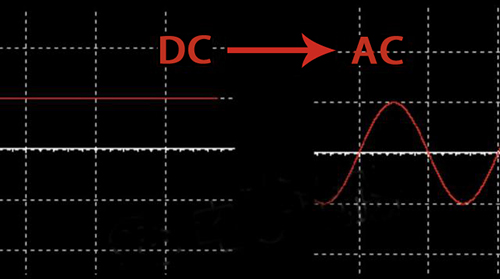
It is very easy to change alternating current (AC) into direct current (DC), and with only a diode, the simplest rectifier circuit can be formed. However, it is not that simple to change direct current to alternating current. The magnitude and direction of alternating current will change periodically over time. The mains power we use shows regular changes of sine function.
Pulse Width Modulation
PWM is the abbreviation of Pulse Width Modulation, which is a very effective technology that controls analog circuits using the digital output of a microprocessor. The basic principle of PWM is that as long as the waveform and the shadow area enclosed by the coordinate axis is the same, they all have the same effect regardless of the shape generated from the voltage waveform. This is the area equivalence principle.
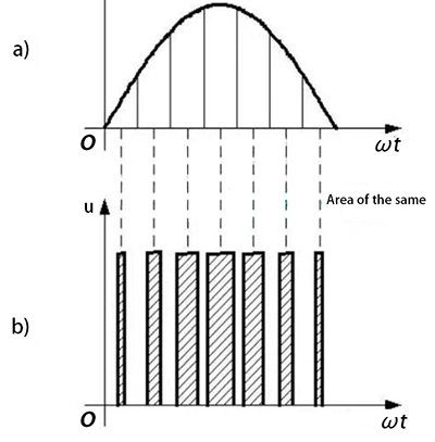
In the above figure, the average voltage of sine wave and square wave output by inverters are the same.
1. The duty cycle of PWM
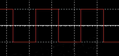
The commonly used PWM is a rectangular pulse (square wave) waveform. The following figure shows a square wave with of 5V amplitude and a frequency of 50Hz.
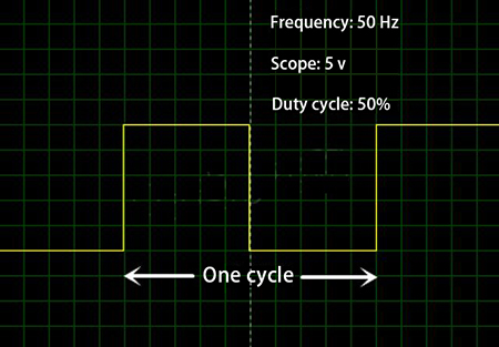
The duty cycle indicates the proportion of the high level in the entire cycle. In the above figure of PWM, the proportion of the high level in this cycle is 50%, so the duty cycle is 50%. Under the condition that PWM has certain frequency, the output voltage can be changed by changing the duty cycle. For example, when the duty cycle is 100%, the output voltage is 5V, and when the duty cycle is 0, the output voltage is 0. When we want to output a voltage of 2.5V, we only need to change the duty cycle to 50%.

2. Resolution
Resolution indicates the minimum value that PWM can achieve, meaning the number of parts that are divided in a period. If it is 10 parts, then the accuracy of the duty cycle is 10%. If it is divided into 1000 parts, the accuracy of the duty cycle is 0.1%.
3. Pure sine wave alternating current of inverter
Although inverters output square waves can be applied to many electrical appliances, some electrical appliances are not. Therefore, inverters that output pure sine wave AC power are needed. Let's take a look at how the inverter generates pure sine wave alternating current.
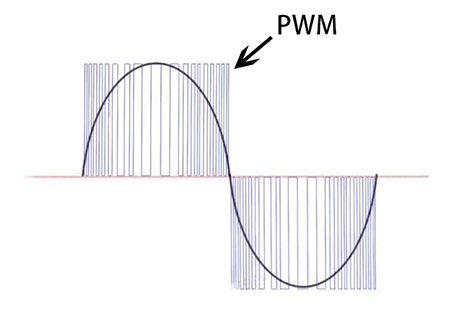
As shown in the figure above, the duty cycle of the PWM changes according to the sine rule. PWM with a large duty cycle is generated in the place where the voltage amplitude is large, and a PWM with a small duty cycle is generated in the place where voltage amplitude is small. During a short time, the average output voltage of PWM is shown by the red line, which can be seen that the waveform has produced a waveform similar to a sine wave. The more precise the PWM is, the smoother the sine wave.
Inverter Square Wave
Let us look at square wave alternating current. The following figure shows the waveform of square wave alternating current.
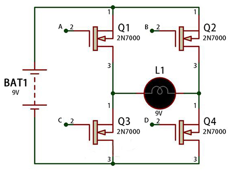
In fact, the alternating current output by the old inverter is the square wave form of the alternating current above. Square wave alternating current is suitable for the equipment with less strict requirements. Let's take a look at how DC power changes to square wave AC power. In the figure below, when the switches S1 and S4 are closed, the direction of the current is like this.
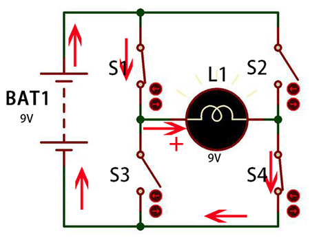
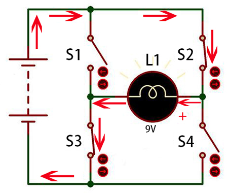
When S2 and S3 are closed, the direction of the current is like this. It can be seen that the direction of the current on the load has changed, thus generates a square wave alternating current.
We know that the frequency of the mains is 50Hz, which means that we with turn on and off the switch 100 times per second. We can use a semiconductor switch (MOS tube) to control the on and off actions of the circuit, as shown in the figure below. By inputting control signals at points A, B, C, and D, the on and off of the MOS tube can be controlled, thus current Direction of the load can be changed and wave alternating current square can be output.