To a solar energy grid-tie system, the time and climate will cause changes of solar radiation, thus resulting in constant changes of the power point voltage. In order to improve the generating capacity, and ensure that the solar panels can output the highest power, either when the sunshine is weak or when the sunshine is strong, the solar inverter usually introduces the boost circuit to expand the voltage of its working point.
 Now let me make a brief introduction why the boost circuit is used, and how the boost circuit helps the solar power system increase the generation capacity.
Why is the boost circuit necessary?
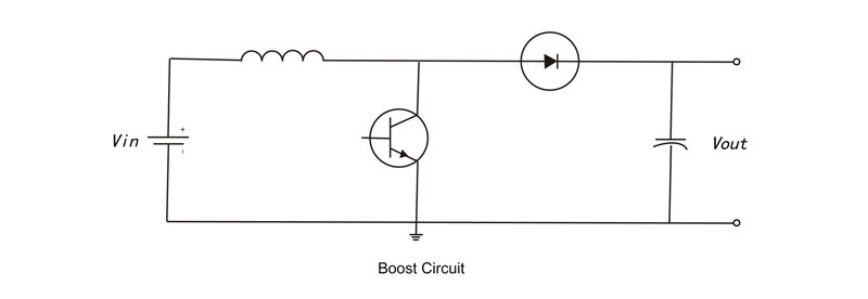
First, let us take a look at the composition of a commonly-seen solar inverter on the market, which is made up of the boost circuit and the inverting circuit. These two parts are connected by the DC bus.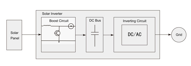
To ensure the inverting circuit to work normally, the DC bus voltage must be higher than the peak value of the grid voltage (the three-phase system is higher than the peak value of the line voltage) so that the power can guarantee positive output to the grid. For the sake of efficiency, the DC bus changes with the grid voltage to ensure it higher than the grid.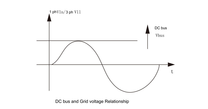 When the solar panel voltage is higher than the voltage needed by the bus, it directly make the part of inversion start operation. The inversion can have MPPT voltage constantly track the maximum point, but after reaching the minimum requirement of the bus voltage, the MPPT voltage cannot drop anymore nor reach the maximum efficiency point. The extremely low scope of MPPT will largely impair the power generation efficiency, thus being unable to guarantee user earnings. Therefore, there should be a method to make up the defect, and the engineer has made use of the boost circuit to achieve this objective.
![]() How does the boost circuit expand the scope of MPPT to increase the power generation?
How does the boost circuit expand the scope of MPPT to increase the power generation?
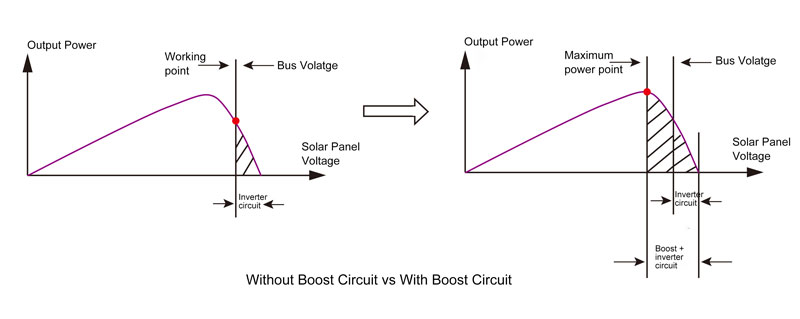
When the voltage of the solar panel is higher than the voltage required by the bus, the boost circuit will be in a rest status, whose energy can be transmitted to the inversion part via the diode. At the same time, the inversion part, after finishing MPPT tracking and reaching the voltage required by the bus, will no longer undertake the MPPT work. At the moment, the boost part can track MPPT via MPPT’s control right, and lift the bus to ensure its voltage.![]() With a broader tracking scope of MPPT, the inversion system can play an important improving role when the solar panel voltage is inadequate during the morning, at dusk or on overcast and rainy days. The following chart shows an obvious improvement of the real-time power.
With a broader tracking scope of MPPT, the inversion system can play an important improving role when the solar panel voltage is inadequate during the morning, at dusk or on overcast and rainy days. The following chart shows an obvious improvement of the real-time power.
 Why does a high power solar inverter use multiple boost circuit to increase the circuit number of MPPT?
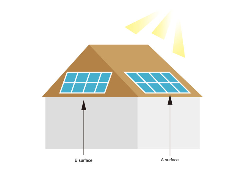
Take a 6kW solar power system for example. The 6kW system is divided into two 3kW solar panels and separately installed on the roof of the two surfaces (See figure below). And now the solar inverter with two-circuit MPPT must be chosen due to the existence of two independent maximum power points. The sun rises from the east in the morning, and then casts its light directly on the A surface of the solar panel, thus increasing the voltage and power of the A surface to a high level. In contrast, the voltage and power of the B surface are much lower. The opposite phenomena are observed in the afternoon. When the voltage of the two circuits is different, the circuit with lower voltage must transmit the energy to the bus to guarantee it to work at the maximum power point.