In our daily life, most electronic products are used through 110V or 220V AC by switching power supply or some other rectifier circuit to convert AC to DC, and the so-called inversion is the process of converting DC to AC, which is a reverse process of rectifier conversion, so the inverter is named after this. Inverters bring us a lot of convenience in our life, such as outdoor barbecue, outdoor lighting, car refrigerators, etc., which are all used by converting DC power in storage batteries into AC power through inverters. Let's learn about the basic working principle of power inverter.
Working principle
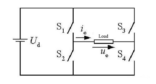
As shown above, it is a typical equivalent diagram of power inverter. In the figure, four switches from S1 to S4 constitute two bridge arms, of which S1 and S2 shares the same bridge arm, and S3 and S4 shares the other same bridge arm. When S1 and S4 are connected, and S2 and S3 are disconnected, Uo = Ud can be obtained on their load resistance. On the contrary, when S2 and S3 are connected, and S1 and S4 are disconnected, Uo = -Ud can be obtained on the load resistance. By continuous operation with switch like this, the AC waveform can be obtained on the load, which completes the process of converting DC into AC, as shown by the following figure.
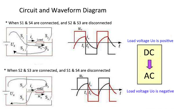
It should be noted that the switch on the same bridge arm cannot be connected simultaneously, so as to avoid short circuit of power supply, and that the frequency of AC can be changed by changing the switch frequency. In fact, the four switches in the figure above are ideal models for various semiconductor switching devices, and common semiconductor switching devices in inverters include thyristors, field effect transistors and insulated gate bipolar transistor (IGBT). For example, the following figure is a switching circuit consisting of a field effect transistor.
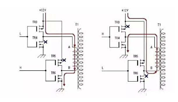
As shown in the figure, the switching device of the circuit is composed of N-channel field transistor and P-channel enhancement field effect transistor, which forms push-pull output. When the driving signal is low-level L, it is the P-channel field effect transistor, and when the input signal is high-level H, it is N-channel field transistor. This alternating conduction can avoid the risk of short circuit caused by the simultaneous conduction of two switches from the same bridge arm. The working process is as follows: the field effect transistors of TR3 and TR4 are from the same bridge arm, TR5 and TR6 are from the other same bridge arm. The conduction of four switches controlled by pulse signals closes to produce alternating signals, which are applied to the low-voltage winding of the transformer, and the high-voltage winding of the transformer will be induced high-voltage AC, so as to complete the inversion from DC to AC.
Conclusion
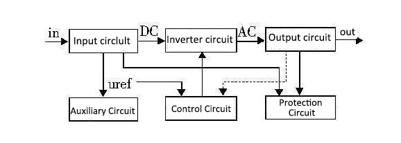
The above is only the basic working principle of inverters. In practice, the application of inverters is absolutely much more complex. An inverter is completely composed of the main circuit, control circuit, drive circuit and auxiliary power supply.
- Main circuit
The main circuit includes various switching circuits to complete the inversion, which are mainly composed of DC power supply (capacitor), buffer, switching bridge circuit, filter and transformer, so as to complete the energy-level processing. - Drive circuit
Drive and ensure the reliable switching on/off of the field effect transistors and other switching devices according to the switching signal of the control board. - Control circuit
Collect feedback from main circuit, realize control algorithm and protection strategy and obtain switch signal. - Auxiliary circuit
Auxiliary power supply and circuit of control chip and driver chip.
In short, the inverter is a device that converts DC power into AC power.