Why does the photovoltaic system generate leakage current?
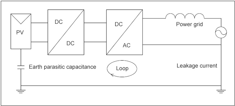
Leakage current of the photovoltaic system, which is also known as the square matrix residual current, is essentially a kind of common mode current. The cause is that there is parasitic capacitance between the photovoltaic system and the earth. When the parasitic capacitance-photovoltaic system-grid forms a loop, the common mode voltage will produce the common mode current on the parasitic capacitance. When the photovoltaic system is equipped with a industrial frequency transformer, because of the relatively high parasitic capacitance between the transformer windings in the loop, the common mode current generated by the common mode voltage in the loop can be suppressed to a certain extent. However, in a photovoltaic system with no transformer, the loop impedance is relatively low, and the common mode voltage will form a large common mode current, ie, leakage current, on the parasitic capacitance between the photovoltaic system and the earth.
Hazard of leakage current
If the leakage current in the photovoltaic system, including the DC part and the AC part, is connected to the grid, it can cause problems such as grid-connected current distortion and electromagnetic interference, so as to affect the operation of the equipment in the grid. In addition, leak current can also electrify the solar inverter casing, thus threatening physical safety.
Standard and detection of leakage current
According to the 7.10.2 regulation of NB32004-2013 standard, in any case where the solar inverter is connected to the AC grid and the AC breaker is turned off, the inverter should provide leak current detection. Leak current detection should be able to detect the total (including the DC and AC parts) effective value current, continuous residual current. If the continuous residual current exceeds the following limits, the inverter should be disconnected and send a fault signal within 0.3s:
- For the inverter with a rated output less than or equal to 30KVA, 300mA.
- For the inverter with a rated output greater than 30KVA, 10mA/KVA.
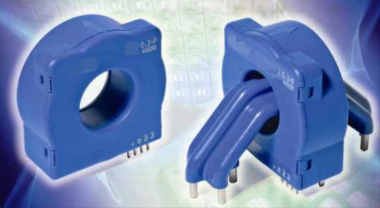
There are two characteristics of photovoltaic system leak current. First is the complex ingredient. There are both DC parts and AC parts. Secondly, the current sub-value is very low, which is in the milliamp level. And it has an extremely high precision requirement, a special current sensor is required. The photovoltaic standard stipulates that for the detection of photovoltaic leakage current, Type B, that is, a current sensor capable of measuring both AC and DC leakage currents, must be used. The current sensor is installed on the external line output interface of the inverter, so as to detect the current of the solar inverter output ground electrode.
Leakage current control technology
At present, leak current suppression technology has become a hot issue in the research of photovoltaic grid-connected systems. Research institutes and manufacturers are studying on it. The magnitude of leak current depends on the parasitic capacitance Cpv between photovoltaic PV and earth, as well as the change rate of the common mode voltage. The value of parasitic capacitance is related to the external environmental condition, photovoltaic cell size and structure and other factors. It usually values around 50~150nF/kW. The change rate of the common mode voltage is related to the topological structure, modulation algorithm of the solar inverter and other factors.
As to the traditional single-phase / three-phase PV grid-tied inverter topology with no transformer, the two basic conditions for effective suppression of common mode current (leak current) are: Consistently select the inductance values of the bridge arms, synthesize the non-zero vectors into the reference vector to maintain constant common mode voltage.
1. Entire H4 bridge topology
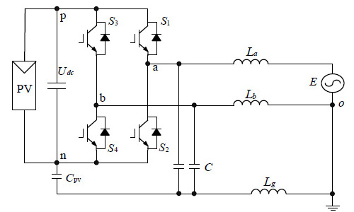
In order to solve the problem of leakage current in a full H-bridge PV inverter, bipolar PWM modulation can be used. This kind of modulation eliminates the high frequency component of the common mode voltage to the board, so that the common mode voltage generally has only the low frequency component of the first harmonic, thereby reducing the effects of leak current.
2. H5 topological structure
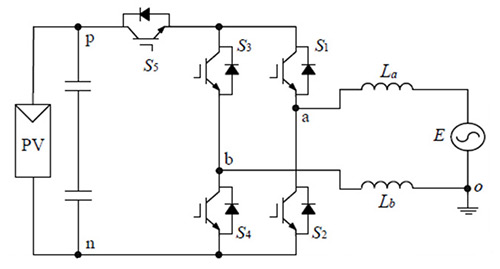
This topological structure requires to add only one additional transistor compared to the full-bridge type. This is the reason of naming it H5. The photovoltaic cell is disconnected from the grid during current freewheeling to prevent the panel pole-to-ground voltage from fluctuating with the switching frequency, thereby keeping the common mode voltage almost constant.
3. HERIC topology
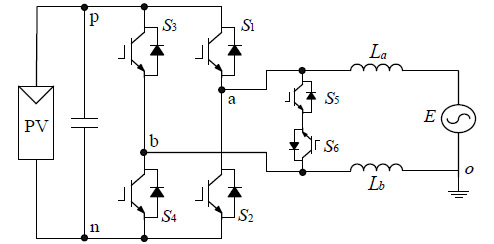
The HERIC AC bypass topology has the following working principle: During the positive half cycle, the switch S5 is always off and S6 is always on, and S1 and S4 are modulated by the switching frequency. When S1 and S4 are turned on, the constant voltage is Udc and 0 respectively, and the common mode voltage = Udc/2. When S1 and S4 are off, the current flows through the antiparallel diodes of S6 and S5, and the constant voltage is Udc/2, and the common mode voltage = Udc/2 at this moment.
4. H6 topological structure
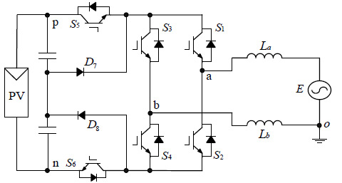
H6 DC bypass topology has the following working principle: In the positive half cycle, the switches S1 and S4 are always on, and S5, S6 and S2, S3 are alternately turned on. When S5 and S6 are on, S2 and S3 are off, then the common mode voltage = Udc/2. When S2 and S3 are on, and S5 and S6 are off, there are two current freewheeling paths: (1). S1 , S3 anti-parallel diode, (2). S4, S2 anti-parallel diode. Diodes D7 and D8 clamp the voltage to Udc/2, and the common mode voltage = Udc/2 at this moment. The common mode voltage in the negative half cycle is also Udc/2, so the leak current can be effectively suppressed.
All the topological structures above reduce the leak current by lowering the common mode voltage. Multi-level technology such as 3-level or 5-level can also be used reduce the grounding voltage of the positive and negative components, thus reducing leak current.