IGBT is a kind of power device, which assumes the function of power conversion and energy transmission in the power inverter. It is the heart of the inverter. At the same time, IGBT is also one of the most unreliable components in the power inverter. It is very sensitive to the temperature, voltage and current of the device. In case of even a slight stand exceeding, it becomes incompetent and cannot be repaired. IGBT damage means the inverter must be replaced or overhauled. Therefore, IGBT is the key protection object of the power inverter.
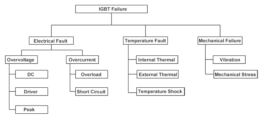
The above is the three modes of IGBT failure. Electrical fault is the most common, because IGBT assumes the function of current and voltage conversion, and the frequency is very high. A too high IGBT main circuit, a too high driving voltage, or a too high external spike voltage may cause overvoltage damage. In addition, overload or short circuit of the power inverter may cause overcurrent. The second is the temperature fault. The IGBT generates a lot of heat during the operation. If the heat cannot be dissipated in time, it may be damaged by overheating. The mechanical failure is likely to be generated in the manufacturing, processing, transportation and installation processes. Such a condition is quite rare.
1. IGBT drive protection
The IGBT itself is a current switching device. When is it turned on, when is it turned off, how long it is on or off is controlled by the CPU of the inverter. However, the DSP puts out a PWM signal, which has a fast speed but insufficient power. The main function of the driver is to amplify the PWM signal.
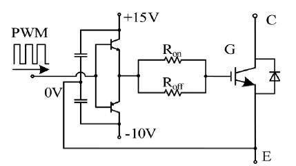
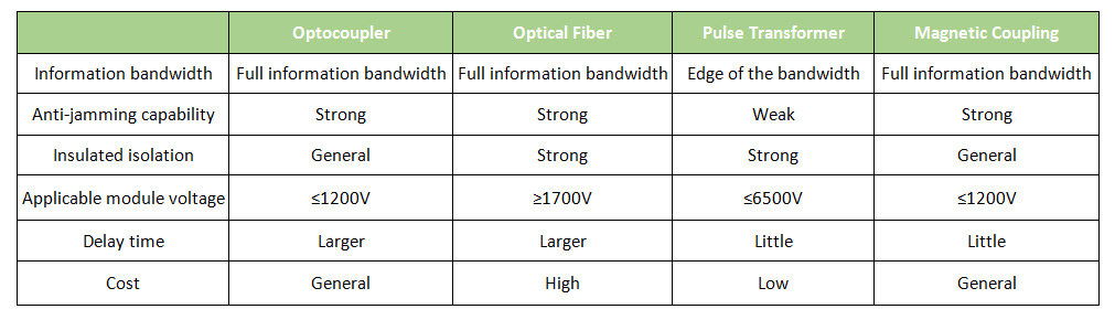
The IGBT controls a very high high-frequency current, and it generates the electromagnetic interference signal. In addition, since the driver is close to the IGBT, the driving circuit must have an isolation function. At present, the driving isolation schemes include the optocoupler, optical fiber, pulse transformer, magnetic coupling and so on. The advantages and disadvantages of each method are as follows:
2. IGBT overcurrent / short circuit protection
In designing the IGBT, the current is usually given a margin of more than 10%. However, when the power inverter is working, due to the short circuit of the component and load, the load side fault causes overcurrent, and the load side has a particularly large inductive load. When starting and stopping, there will be a high harmonic current. At this time, the inverter output current will rise sharply, causing the operating current of the IGBT to rise sharply. The IGBT short circuit is divided into two cases: The through-current occurs in the bridge arm of the converter, which is called the type-I short circuit. The short-circuit point of the converter occurs on the load side, and the equivalent short-circuit impedance is high, which is called the type-II short circuit. The type-II short circuit can generally be considered as a serious overcurrent in the inverter. When the short circuit occurs, if the relevant measures are not taken, the IGBT will quickly enter the desaturation, and the transient power consumption will exceed the limit and be damaged, because the IGBT can only sustain the overcurrent for only a few microseconds. Therefore, when a short circuit occurs, the IGBT should be turned off as soon as possible, and the turn-off speed should be gentle, so as to ensure that the rate of current change is within a certain range, thus avoiding the voltage being cut too fast, causing the voltage stress to exceed the limit and damaging the IGBT. The active clamping scheme is provided with the quick response measure, which enables the IGBT driver to operate as quickly as possible.
3. IGBT over-temperature protection
When the ambient temperature of the power inverter is too high, or the inverter has a poor heat dissipation, continuous overheating will damage the IGBT. If the device continues to have short-circuit, the power generated by the high current will cause a temperature rise. If the chip temperature exceeds the silicon intrinsic temperature (about 250 °C), the device will lose its blocking capability, and the gate control will not be protected, resulting in IGBT failure. Two aspects are mainly considered in designing: First, strengthen and improve the heat dissipation condition of the IGBT tube, including air duct design, heat sink design and production, and strengthen refrigeration and so on; second, design overheat detection protection circuit, adopt the built-in thermistor on the IGBT module to measure the IGBT heat dissipation temperature. It is very accurate. When the temperature exceeds the set value, the IGBT will be turned off to stop working.
4. IGBT mechanical failure protection
In order to facilitate heat dissipation, the IGBT is connected by screws and mounted on the radiator. The connection strength of this screw is very particular, which should be appropriate. If the force is too strong, it will damage the IGBT. If the force is too light, during the transportation and installation process, the vibration will cause poor contact, the thermal resistance will increase, and the device will have over-temperature damage. In installing the IGBT, a special screwdriver will be used. According to the IGBT model, the corresponding torque is used to ensure that the IGBT is firmly connected and not be damaged easily.
Conclusion
IGBT is the most sensitive and vulnerable device in the power inverter. At the same time, it is also the most expensive and critical component in the inverter, and many different measures should be taken to protect it.