Photovoltaic inverter is an important equipment in the photovoltaic system, the main role is to convert the direct current emitted by the photovoltaic module into alternating current. In addition, the inverter is also responsible for the detection of components, power grid, cable running state, and external communication and other important functions.
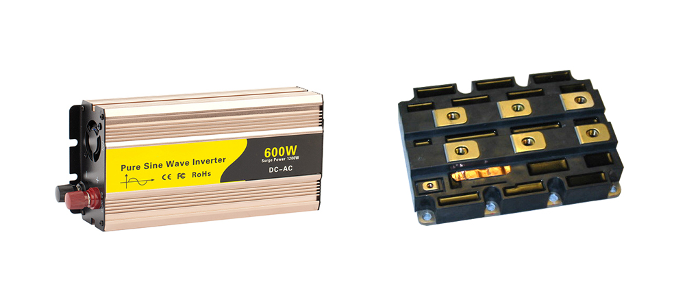
As a power device, IGBT (insulated gate bipolar transistor) plays the role of power conversion and energy transmission in the inverter, and is the heart of the inverter. At the same time, IGBT is one of the most unreliable components in the inverter, which is very sensitive to the temperature and current of the device. Therefore IGBT is the key protection object of power inverter.
The core use of IGBT protection technology in photovoltaic inverter is reflected in four aspects. In the following, Inverter.com will introduce to you.
- Driving Protection. IGBT is a current switch device, how long the switch is controlled by the CPU of the inverter, but the DSP output is a PWM signal, the speed is very fast, but the power is not enough, the driver's most important role is to amplify the PWM signal. IGBT control a large current, will produce electromagnetic interference signals, and the driver and IGBT separated by very close, so the drive circuit to have isolation function. At present, there are several driving isolation schemes, such as optical coupling, optical fiber, pulse transformer and magnetic coupling.
- Over-current / Short-circuit Protection. In the design of IGBT, the current will generally leave a margin of more than 10%. However, when the pure sine wave inverter is working, due to the component, the load short circuit leads to overcurrent, the load side has a particularly large inductive load, there is a large harmonic current when the start and stop, this time the output current of the inverter will rise sharply, resulting in the IGBT working current will also rise sharply.
- Over-temperature Protection. If the ambient temperature of the inverter is too high and the heat dissipation of the sine wave inverter is poor, continuous overheating will lead to IGBT damage. If the device is continuously short-circuited, the power dissipation from the large current will cause the temperature to rise. If the chip temperature exceeds the silicon temperature (about 250 ℃), the device will lose its blocking ability and the gate control will not be protected, resulting in IGBT failure. So in the design mainly from two aspects to consider. First, strengthen and improve the IGBT pipe heat dissipation conditions, including air duct design, radiator design and production. Second, the design of overheating detection circuit, with IGBT module built-in thermistor to measure the IGBT heat dissipation temperature, is very accurate. When the temperature exceeds the set value, turn off the IGBT to stop working.
- Mechanical Fault Protection. In order to facilitate heat dissipation, IGBT is connected by screws, installed on the radiator, the connection strength of the screws should be just right, neither too strong, nor too light strength. If the force is too strong, it will damage the IGBT. If the force is too light, in the process of transportation and installation, due to vibration will cause poor contact, increase of thermal resistance, device overtemperature damage. Therefore, when installing IGBT, a special screw batch will be used. According to the IGBT model, the corresponding torque will be used to ensure that the connection is firm and not damaged at the same time. IGBT is the most easily damaged part of the inverter, but also the most expensive, the most critical part of the power inverter. Therefore, in order to be able to better protect IGBT, inverter must take more corresponding protection measures.