Frequency inverters can be used in home appliances. Among the home appliances that use a frequency converter are not only motors (e.g., air conditioners, etc.) but also products such as fluorescent lamps. Frequency inverters used for motor control can change both voltage and frequency. The operating principle of inverters is used in a wide variety of fields. For example, the power supply for computer power supplies, in which the frequency converter is used to suppress fluctuations in reverse voltage, frequency, and momentary power outages. Inverter shop will introduces the working principle of frequency inverter, control mode, and working process.
Frequency Inverter Working Principle
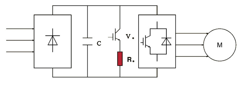
- Rectifier Part: Usually also known as the grid-side converter part, it is to rectify the three-phase or single-phase alternating current into direct current, and through the rectification again (that is, the inverter part) into alternating current. The common low-voltage rectifier part is composed of a diode uncontrollable three-phase bridge circuit or a three-phase controllable bridge circuit composed of thyristors. For the medium voltage large capacity rectifier part is used to multiply 12 pulses or more converter.
- DC Link: As the load of the inverter is an asynchronous motor, which belongs to inductive load, there is always no power exchange between the intermediate DC part and the motor, and this exchange of no energy is generally required to buffer the intermediate DC link of the energy storage components (such as capacitors or inductors). DC intermediate circuit of the rectifier circuit output for smooth filtering, DC energy storage, and buffer reactive power.
- Inverter Section: Often also referred to as the load-side converter section, it realizes the regular turn-off and conduction of the inverter elements through different topologies to obtain a three-phase AC output at any frequency. A common inverter section is a three-phase bridge inverter circuit consisting of six semiconductor main switching devices, and the output is a PWM waveform.
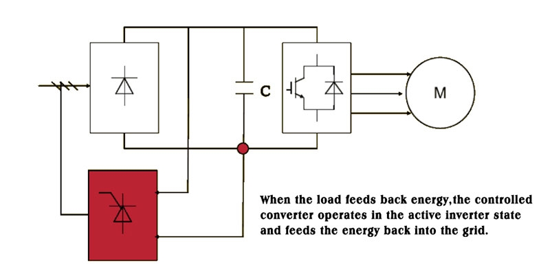
- Braking or Feedback Link: As the regenerative energy formed by braking in the motor side is easy to gather to the DC link of the inverter to form a DC bus voltage pumping, the need for timely release of energy in the form of heat through the braking link or converted to the AC grid through the Feedback Link. Braking links in different inverters have different realization methods. According to the power, the size can be a built-in braking unit and an external braking unit. The feedback link mostly belongs to the external circuit of the frequency inverter.
Braking Methods for Frequency Inverters
Energy Consumption Braking: When the pump-up voltage exceeds a certain value, V. conducts, thus consuming the energy fed back by the load on R.
Energy Feedback Braking: When the load feeds back energy, the controllable converter works in the active inverter state and feeds the energy back to the grid.
Frequency Inverter Control Mode
V/f Control
V/f control is to get the ideal torque-speed characteristics, based on the change of power frequency for speed regulation at the same time, but also to ensure that the motor flux is unchanged and put forward the idea, general-purpose frequency converter adopts this kind of control. v/f control frequency converter structure is very simple, but kinds of frequency inverter adopts the open-loop control mode, and can't achieve a higher control performance, moreover, in the low-frequency, there must be torque compensation to change the low-frequency torque characteristics.
Differential Frequency Control
Differential frequency control is a kind of direct torque control, it is based on V/f control, according to knowing the actual speed of the asynchronous motor corresponding to the power supply frequency, and according to the desired torque to adjust the output frequency of the frequency converter, you can make the motor has the corresponding output torque. In this kind of control method, it is necessary to install a speed sensor in the control system, and sometimes there is also current feedback to control the frequency and current, so it is a kind of closed-loop control method, which can make the frequency converter have good stability and a good response to the rapid acceleration and deceleration, and the load change.
Vector Control
Vector control is to control the magnitude and phase of the motor stator current through the vector coordinate circuit to control the motor excitation current and torque current separately, and then to achieve the purpose of controlling the motor torque. By controlling the order and time of the action of each vector and the time of the action of the zero vector, various PWM waves can be formed to achieve different control purposes. For example, to form the PWM wave with the least number of switching times to reduce the switching loss. At present, the vector control methods applied in the inverter mainly include the vector control method based on the rotational frequency control and the vector control method without a speed sensor.
Direct Torque Control
Direct torque control uses the concept of space vector coordinates to analyze the mathematical model of the AC motor under the stator coordinate system to control the magnetic chain and torque of the motor, and achieves the purpose of observing the magnetic chain of the stator by detecting the stator resistance, thus eliminating the complicated transformation calculations, such as vector control, and the system is intuitive and concise, and the speed of calculation and the accuracy are both improved compared with the vector control method. The system can output 100% of the rated torque even in the open-loop condition, and it has the function of load balancing for multiple drags.
Optimal Control
The application of optimal control in practice varies according to different requirements, and individual parameters can be optimized according to the theory of optimal control for a certain control requirement. For example, in the control of high-voltage inverters, two strategies of time segmentation control and phase shift control have been successfully adopted to realize the optimal waveform of voltage under certain conditions.
Frequency Inverter Working Process
- Parameter Setting: Before starting the inverter, it is necessary to set its parameters. These parameters include the rated power, rated voltage, and rated current of the motor. The setting of parameters directly affects the output performance of the inverter.
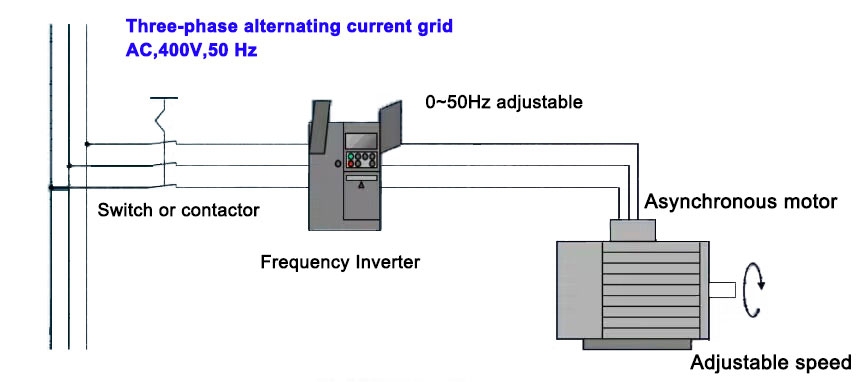
- Input Power: The frequency inverter receives AC power through the input rectifier and converts it to DC power. The intermediate DC link smoothes the DC power to ensure the stability of the power supply.
- Inverter Output: The frequency inverter converts DC power to adjustable frequency AC power and outputs it to the motor. Through the control of the inverter, precise adjustment of the motor speed can be realized.
- Control System Adjustment: The control system adjusts the inverter output according to the real-time monitored parameters such as current, voltage, and speed. The closed-loop control system can make the motor run stably under different loads and working conditions.
- Real-time Feedback: The control system of the inverter can provide real-time feedback on the running status of the motor, and ensure that the motor runs according to the predetermined speed and torque through monitoring and adjustment.
As the core component of modern motor control system, frequency inverter not only plays a key role in the industrial field but also in the energy field, transportation, and other fields to show broad application prospects. In the future, with the continuous development of technology, frequency converters will be more intelligent and efficient, providing more reliable and flexible motor control solutions for various industries.