Three-phase inverters play a crucial role in converting direct current (DC) power into alternating current (AC) in various applications, from industrial machinery to renewable energy systems. Understanding the fundamental workings of these inverters is essential for appreciating their significance and diverse applications.
Basic Knowledge
A three-phase inverter circuit is commonly used in high-capacity applications due to constraints related to the capacity of power switching devices, neutral line current, grid load balancing requirements, and characteristics of electrical loads. Single-phase inverter circuits, limited to capacities below 100 kVA, face these restrictions. Three-phase inverters, on the other hand, are employed for larger capacities and can be categorized into three-phase voltage-type inverters and three-phase current-type inverters based on the nature of the DC power source.
Three-Phase Voltage-Type Inverter
In a voltage-type inverter, the input DC energy for the inverter circuit is supplied by a stable voltage source. Its distinctive feature is that the amplitude of the output voltage during pulse width modulation equals the amplitude of the voltage source. The current waveform, however, depends on the actual load impedance. The basic circuit of a three-phase voltage-type inverter is illustrated in Figure 1.
Figure 1: Three-Phase Voltage-Type Inverter Circuit Diagram
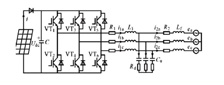
In this circuit, six power switching devices (VT1 to VT6) and six freewheeling diodes are controlled by the control circuit. When the control signals are three-phase pulse signals with a 120-degree phase difference, each power switching device can be controlled to conduct for 180 or 120 degrees. The conduction time of adjacent switching devices differs by 60 degrees. The upper and lower switching elements of the three bridge arms alternate between conducting and turning off at 180-degree intervals. VT1 to VT6 are turned on and off sequentially with a 60-degree potential difference, forming three-phase voltages (a, b, c) at the inverter output.
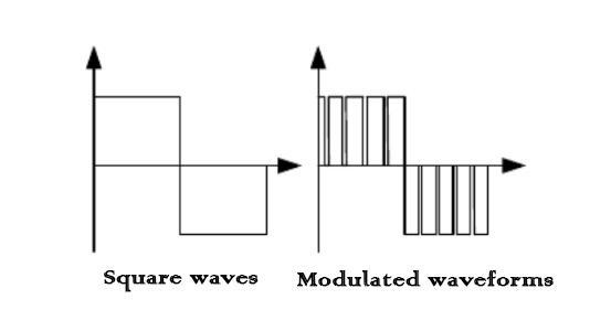
The switch control signals for the control circuit output can take the form of square waves, step waves, pulse width modulated square waves, pulse width modulated triangular waves, and sawtooth waves. Among these, the last three waveforms are modulated using a sinusoidal wave as the carrier and a sine wave as the modulating wave, ultimately producing a sinusoidal waveform as the output. The distinction between a regular square wave and a sinusoidally modulated square wave is illustrated in Figure 2. In comparison to a regular square wave signal, the modulated square wave signal follows a series of square wave signals in accordance with the sinusoidal wave pattern. In other words, the regular square wave signal is continuously on, while the modulated square wave signal undergoes N cycles of on and off within the modulation period of the sinusoidal wave.
Figure 2: Square waves and modulated waveforms
Three-Phase Current-Type Inverter
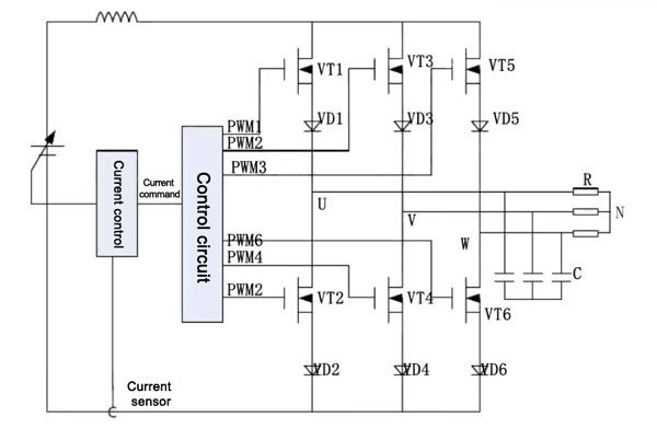
In a current-type inverter, the DC input power source is a constant DC current source, and the modulation is applied to the current. If a rectangular current is injected into the load, the voltage waveform is generated under the influence of the load impedance. In current-type inverters, there are two different methods to control the amplitude of the fundamental current. One method is the amplitude modulation of the DC current source, which simplifies the current control on the AC output side. The other method involves using pulse width modulation to control the fundamental current. The basic circuit of a three-phase current-type inverter is depicted in Figure 3.
This circuit comprises six power switching devices, six freewheeling diodes, a constant DC current source, surge absorption capacitors, and other components, with R representing the electrical load.
Figure 3: Three-Phase Current-Type Inverter Circuit Diagram
Characteristics of Current-Type Inverter
The current-type inverter is characterized by having a large filtering inductance on the DC input side. When the power factor of the load changes, the AC output current waveform remains unchanged, meaning the AC output current waveform is independent of the load. Unlike the voltage-type inverter in circuit structure, where each power switching element is parallel to a freewheeling diode, the current-type inverter has a reverse-blocking diode connected in series with each power switching element.
Similar to the three-phase voltage-type inverter circuit, the three-phase current-type inverter consists of three sets of upper and lower pairs of power switching elements. However, the switching method is different from the voltage-type. The inclusion of a large inductance L in series with the DC input minimizes fluctuations in the DC current. When the power switching elements perform switching actions, the current remains stable and continuous. Consequently, one of the upper switching elements VT1, VT3, VT5, and one of the lower switching elements VT2, VT4, VT6 can conduct a certain value of current in intervals of 1/3 of a cycle. The output current waveform is a square wave during the 120-degree energization period with a height equal to that current value. Additionally, to prevent rapid changes in current when connecting inductive loads, surge absorption capacitors (C) are connected in parallel at the inverter's output.
The DC power source of the three-phase current-type inverter, i.e., the DC current source, is achieved through a variable voltage source using current feedback control. However, employing only current feedback cannot reduce the power ripple in the inverter input voltage caused by switch actions, resulting in current fluctuations. Therefore, a large inductance (reactor) L is connected in series at the power input to mitigate these effects.
Current-type inverters are well-suited for grid-connected systems, particularly in solar photovoltaic power generation systems, where they offer unique advantages.
For more information on inverters, please visit inverter.com.