A single phase output inverter is an electronic device designed to convert direct current (DC) power into single-phase alternating current (AC) power. In other words, it takes electrical energy from a DC source, such as a battery, solar panel, or DC power supply, and produces a single sinusoidal waveform of AC power.
One of the important applications of inverters is that they can be used to adjust the speed of AC motors. As long as the frequency of the excitation current in the motor's excitation coil is changed, then the rotational frequency of the magnetic field in the motor is also changed, and the magnetic field frequency is changed, then the motor's rotational speed will be changed. Another important use of inverters is in industrial smelting furnaces, where the body of the furnace is heated by the action of coils with high-frequency currents (eddy current effect), which in turn smelt the minerals in the furnace.
The principle of a single-phase inverter is an H-bridge, the circuit consists of four parts, a 15V DC source, four switching tubes (M1, M2, M3, M4, M1 and M4 are PMOS tubes, M2 and M3 are NMOS tubes), an inductor L1, a switching-tube control power supply (PWM1, PWM2, with PWM1 and PWM2 having the opposite control logic)
Experimental circuit
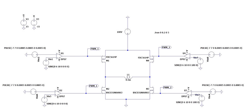
The principle of the H-bridge is that the four switching tubes in the same moment, only the diagonal on the two tubes on the on, another diagonal on the two tubes in the off, the next moment of the two diagonal tubes on and off the logic of the opposite, for example, t = 0s, M1 and M3 are in the on state, M2 and M4 are in the off state; t = 0.5s, M2 and M4 are in the on state, M1 and M3 are in off state. According to the above explanation, then we know that the logic of the control signals controlling M1 and M3 should be the same, the logic of the control signals controlling M2 and M4 should be the same, and the logic of the signals controlling M1 and M3 should be the opposite of the logic of the signals controlling M2 and M4.
If all 4 switching tubes are NMOS, we directly follow the logic explained above to drive the switching tubes directly, but unfortunately, the H-bridge we built uses PMOS for M1 and M4, not NMOS. if we use NMOS, there will be a problem that the ground of M1 and M4 will change with the voltage change of the two ends of the inductors, which is a floating ground, so to drive M1 and M4 normally, we need to use the same logic to control M1 and M4, and the logic of controlling M1 and M3 signals is opposite to controlling M2 and M4 signals. Drive M1 and M4 to use a power supply with a floating ground, it is not impossible to build, but think about the configuration of their computers, instantly no power, so here on the use of PMOS, the use of PMOS do not have to build a separate floating ground power supply.
PMOS turn-on requirements gate (G) voltage than the drain (D) voltage can be lower than 10V, PMOS shutdown requirements gate (G) voltage and drain (D) voltage can be the same; NMOS turn-on requirements gate (G) voltage than the drain (D) voltage is 10V higher than the NMOS shutdown requirements gate (G) voltage equal to the drain (D) voltage can be. See here I guess someone will ask, why 10V? Because the general high-power MOS tube (regardless of PMOS or NMOS) turn-on voltage is generally twice the threshold voltage can be, and the general high-power switching tube threshold voltage of the absolute value is about 5V, so here choose 10V.
Therefore, directly in summary, we add two PMOS control logic is as follows: M1 and M2 consistent, M3 and M4 consistent, M1 and M2 and M3 and M4 control logic is opposite.
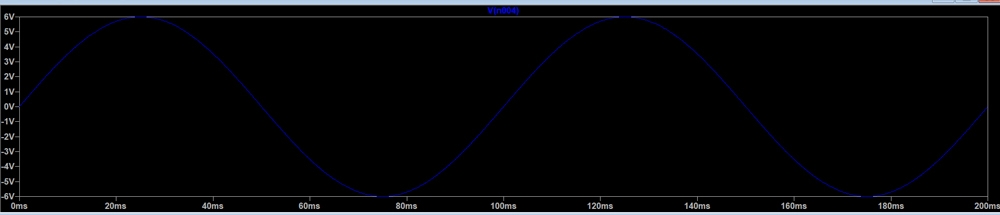
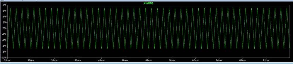
As for the control signal generation, we here use a triangle wave and a sine wave to compare the output control signal PWM, the sine wave is our inverter output reference waveform, the reference waveform frequency is 10HZ, then it also determines the frequency of our inverter output sine wave is also 10HZ.
Reference Sine Wave
Triangle Wave
Inverter Output Sine Wave Display
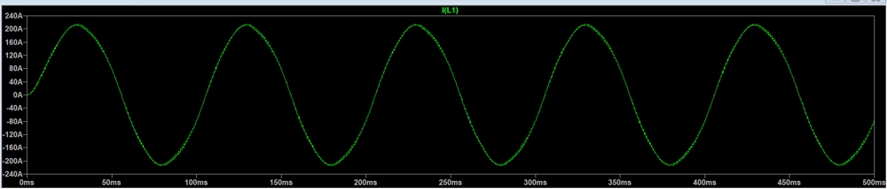
Detailed Display of Inverter Output Sine Wave
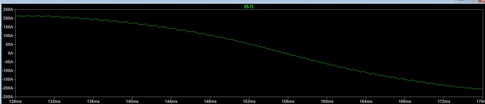
We can see from the simulation output above that the amplitude of the output sine wave is over 200 amps, note that the inverter outputs a current type sine wave, not a voltage sine wave as we normally say! The process of inverting makes use of the principle that the current of an inductor cannot change abruptly, and according to our high school knowledge, the voltage and current at the ends of the inductor meet the requirements:
UL=L*di/dt
Both sides of the time at the same time to integrate: IL = Ut / L
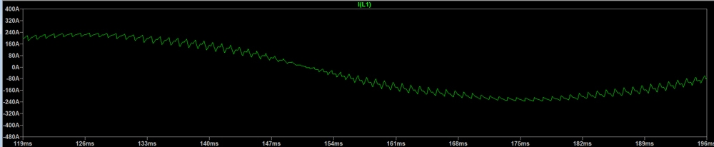
Inductor voltage is constant, that is, our DC power supply 15V, UL = 15V (ignoring the voltage drop of the switching tube), t is each time the switching tube opening time, this time is changing, from the above PWM wave can be seen, L is our inductance 0.3mH, according to the above formula can be calculated every time after the switching inductance above the current changes in the size of the current change, current changes The current change can be seen from the last picture, the inverter output waveform above the jagged change is caused by each switching tube inductance current change, the smaller the inductance current change is more pronounced, we change the inductance from 0.5mH to 0.05mH output waveform is as follows, it is obvious to see that the inductance of the current change is greater, it can also be said that the output of the sinusoidal wave waveform of the ripple is greater.
0.05mH Output Waveform
From the results of the above demonstration, the principle of inverter is not clearer. Inverter is not so complicated, mainly through the switching tube circuit to build a DC power supply for a short period of time to charge and discharge the inductor, the inductor is born with the characteristics of the current will not change suddenly, which means that the inductor will only let the inductor switch each time a small change in the current, which is the subtlety of the DC-AC.
If you need more information about inverters, please visit inverter.com.