In the photovoltaic system, the cost of the solar inverter is less than 5%, but it is one of the decisive factors of power generation efficiency. When the accessories such as the component are completely consistent, if different inverters are selected, the total power generation capacity of the system has a difference ranging from 5% to 10%. Such a difference is mainly caused by the inverter. The MPPT efficiency is the key factor determining the PV solar inverter power generation capacity, and its importance even exceeds the efficiency of the PV inverter itself. The MPPT efficiency is equal to the hardware efficiency multiplied by the software efficiency. The hardware efficiency is mainly determined by the accuracy of the sampling circuit, the MPPT voltage range and the number of MPPT paths. The software efficiency is determined by the control algorithm.
Maximum Power Point Tracking (MPPT for short) is a core technology in photovoltaic power generation system. It means to adjust the output power of the photovoltaic array according to different environmental temperature and light intensity, so that the photovoltaic array could always put out the maximum power.
Accuracy of MPPT sampling circuit
There are a great variety of methods to realize MPPT. However, no matter which method is used, it is firstly required to measure the component power change and then react to the changes. The most critical component in this process is the current sensor. Its measurement accuracy and linearity error will directly determine the hardware efficiency. There are mainly two kinds of current srnsors: closed-loop and open-loop types. The open-loop current sensor is generally the voltage type, which has the small size, light weight, no plug loss, low cost and the linear accuracy of 99%. Its total measurement error is about 1%. As to the closed-loop current sensor, its frequency band scope is wide, the accuracy is high, the response time is fast, and the interference resistance ability is strong. Its linear accuracy is around 99.9% and the total measurement error is 0.4%.
When the weather condition changes fiercely, the closed-loop sensor has advantages.
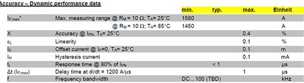
Closed loop current sensor
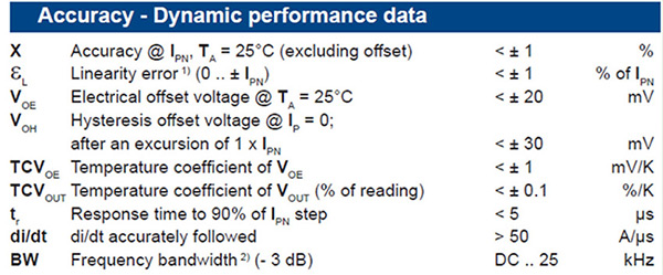
Open loop current sensor
MPPT voltage scope
The operating voltage range of the power inverter is related to the electrical topological structure of the inverter and the output voltage of the inverter. The string inverter and the distributed inverter adopt the two-stage electrical topological structure. The MPPT operating voltage range is within 250-850V. The centralized inverter adopts the single-stage structure, and its output voltage has 270V, 315V, 400V and other specifications. The input MPPT has the voltage ranges of 450-850V, 500-850V, 570-850V and so on, and there is a string inverter in the single-stage structure, which has only one DC-AC inverter. Its output voltage is 400V, and the MPPT input voltage range is 570-850V. From an application point of view, each inverter has its own advantages and disadvantages.
- From the perspective of the inverter, as to the inverter with a higher output voltage, if the power grade is the same, a lower current tends to have a higher efficiency. Compared with the two-stage structure, the single-stage structure has a simpler structure, higher reliability, lower cost, and cheaper cost.
- From the perspective of the system, if the inverter has a wider MPPT voltage scope, it can be started earlier and stopped later, and the power generating time is longer.
- According to the voltage source series connection principle, the system output voltages are added and the current is unchanged. After the PV modules are connected in series, the output current is determined by the minimum number of panels. Due to the influence of the component raw material, processing technology, shadow, dust and so on, if the power of one component is reduced, the power of this series of components will be reduced. Therefore, the number of components connected in series should be fewer and the number of components connected in parallel should be more, so as tor educe the influence brought by component consistency.
MPPT loops
At present, the string inverter has a number of 1-5 MPPT loops, and the power frequency centralized inverter also has 1-3 MPPT loops. The distributed inverter integrates the combiner box and the MPPT boost. There are multiple MPPTs, and there is also a high-frequency modular centralized inverter. Each module has an MPPT. This solution was launched by Emerson in 2010. However, the market response is not too ideal probably because of the immature technology at that time.
From the perspective of solving the mismatch problem, the more MPPT is, the more favorable it is. From the perspective of the stability and efficiency, it is better to have fewer MPPTs, because the increased MPPT quantity tends to result in a higher system cost, poorer stability and more loss. Therefore, it is necessary to select an appropriate solution in combination with actual terrain requirements. In theory, the inconsistency of components should exceed 0.5%, then there is some operation values.
- Functional loss: There are many MPPT algorithms, such as interference observation method, incremental conductivity method, conductance increment method and so on. No matter which algorithm is used, the sunlight intensity is judged by constantly changing the DC voltage, so an error can not be avoided. For example, when the voltage is actually at the optimal operating point, the solar inverter will still try to change the voltage to determine whether it is the best operating point. If there is an increased MPPT loop, there will be more loss.
- Measure the loss: When the MPPT is working, the inverter has to measure the current and voltage. Generally speaking, the larger the current, the greater the anti-interference ability, and the less the error. The 2-loop MPPT has the current 2 times as much as that of the 4-loop MPPT, and the error is reduced greatly. For example, a 50kW solar inverter of a company uses an open-loop DC current sensor HLSR20-P with a current of 20A and an error of 1%. When the input current is less than 0.5A, the error often occurs. When the input current is less than 0.2A, it basically can not work.
- Circuit loss: The MPPT main circuit has an inductor and a switching transistor that also generates losses during operation. generally speaking, a higher current tends to realize lower inductance value and fewer losses.
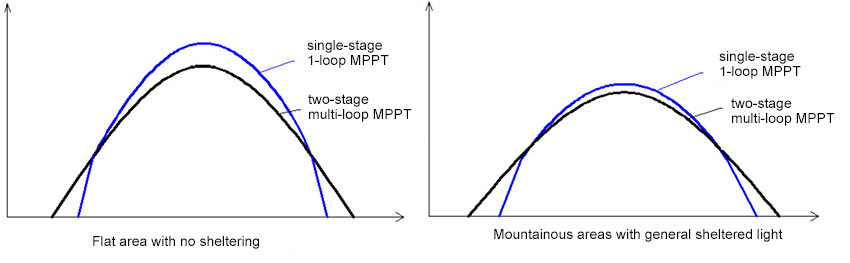
The following figure shows the actual power generation of different MPPT inverters in two different places. It can be seen from the figure that on the flat area with no sheltering, the power generation of the two inverters is similar. In mountainous areas or on roofs with general sheltered light conditions, the inverter of the two-stage multi-channel MPPT has a high power generation capability.
Summary
The diversity of inverter MPPT technology has brought great convenience to power station design. Combined with the actual and scientific design, on different terrains and in different lighting conditions, different inverters will be selected to reduce power station cost and improve economic efficiency. Mountain power stations and rooftop power stations have inconsistent and partial sheltering phenomena, and different mountains have different sheltering characteristics, resulting in component mismatch problems. It is recommended to select the two-stage inverter with multi-channel MPPT and wide voltage range, which can prolong the power generation time in the morning and evening. In flat areas with no sheltering and good lighting conditions, it is recommended to select the single-staged inverter with the single-loop MPPT to improve system reliability and reduce system cost.