A sinusoidal inverter is a type of inverter that converts direct current (from power batteries or storage batteries) into alternating current (generally 220V, 50Hz sine wave). The inverter and AC-DC converter are opposite processes. While AC-DC converters or power adapters rectify 220V alternating current into direct current for use, an inverter does the opposite, hence its name.
A sine wave UPS inverter is an electrical energy conversion device that transforms direct current into alternating current, accomplished by the controlled conduction and switching of power semiconductor devices according to specific patterns. Modern inverter technology is a practical field built upon the theoretical study, application, and design methods of inverter circuits. It relies on the foundation of industrial electronics technology, semiconductor device technology, modern control technology, modern power electronics technology, pulse width modulation technology, semiconductor commutation technology, and magnetic materials, among others. As a result, the applications of sinusoidal inverters span various sectors in society and everyday life.
Basic Structure
A sinusoidal inverter converts direct current into alternating current by controlling the conduction and switching of semiconductor power switches (such as SCR, GTO, GTR, IGBT, and power MOSFET) in a specific sequence. The circuit that controls the conduction and switching of power switches is the inverter's control circuit. The control circuit outputs specific voltage pulses to govern the conduction and switching of the power switches in a defined pattern. This results in a specific harmonic combination in the output of the power main circuit, and the desired voltage waveform is obtained through a filtering circuit. The basic structure of a sinusoidal inverter system is depicted in Figure 1.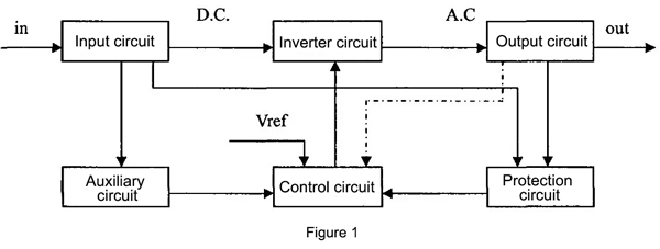
- Input Circuit: The input of an inverter typically consists of direct current (or direct current obtained through rectification and filtering of mains electricity). These direct current sources can include DC grids, batteries, photovoltaic cells, and other means of generating direct current. Usually, these sources cannot be directly used as the input voltage of the inverter and must pass through filtering and EMC circuits before being fed into the inverter.
- Inverter Main Circuit: The inverter main circuit consists of power switching devices and forms the power conversion circuit. The structure of the main circuit varies in different input and output conditions, and each power conversion circuit has its advantages and disadvantages. In practical design, the most suitable circuit topology should be considered as the main circuit structure.
- Control Circuit: The control circuit generates a set or multiple sets of voltage pulses according to the requirements of the inverter's output. These pulses are applied to the power switches through a driving circuit, causing the power switches to conduct or switch off in a specified sequence. Ultimately, the desired voltage waveform is obtained at the output of the main circuit. The performance of the control circuit is critical for the quality of the inverter's output voltage waveform.
- Output Circuit: The output circuit typically includes output filtering and EMC circuits, and if the output is direct current, a rectification circuit is added afterward. For isolated output inverters, a transformer is placed in the front stage of the output circuit. Depending on whether a voltage regulation circuit is needed in the output, the output circuit can be categorized as open-loop or closed-loop control. In an open-loop system, the output is solely determined by the control circuit, while in a closed-loop system, the output is influenced by feedback loops, resulting in a more stable output.
- Auxiliary Power Supply: Certain parts or chips in the control circuit and input/output circuit have specific voltage requirements. An auxiliary power supply is used to meet these specific voltage needs. Typically, the auxiliary power supply consists of one or more DC-DC converters. In cases of AC input, the auxiliary power supply is created by combining the rectified voltage with DC-DC converters.
- Protection Circuit: The protection circuit usually includes protections against input overvoltage, undervoltage, output overvoltage, undervoltage, overload, overcurrent, and short-circuit protection. In specific operating conditions, inverters may require additional protections, such as temperature protection for extremely low or high temperatures, pressure protection for pressure variations, and humidity protection for humid environments.
Types
Inverters can be classified in various ways, and based on the nature of their output waveforms, they can be categorized into three types: sinusoidal inverters, square wave inverters, and trapezoidal wave inverters. Sinusoidal inverters produce sinusoidal alternating current, whereas square wave inverters produce lower-quality square wave AC.
Inverters are typically divided into voltage-input and current-input types. Unlike direct current choppers, their modulation pulses are related to the width of a sine wave, resulting in output current or voltage that closely resembles a sine wave. Because it requires a significant number of inductive components to simulate a current source, current-input inverters are rarely used for electric vehicle propulsion. Voltage-input inverters have a simpler circuit structure and are capable of bidirectional energy conversion, making them the preferred choice for electric vehicles. A typical three-phase full-bridge voltage-input inverter is illustrated in Figure 2.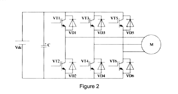
Depending on specific requirements, the output waveform of these inverters can be square wave or pulse width modulated (PWM) waveforms. PWM schemes can further be categorized into sinusoidal PWM, current hysteresis PWM, and space vector PWM. Inverters can utilize PWM technology to generate pulse width modulated waveforms for induction motors and permanent magnet synchronous motors. The appropriate scheme can effectively suppress harmonics, optimize the use of direct current voltage, and reduce voltage fluctuations.
Pure Sine Wave UPS Inverter Principle
The function of an inverter is to convert direct current (DC) into alternating current (AC). It consists of an inverter bridge, a SPWM (Sine Pulse Width Modulation) waveform generation module, a driver module, and a filtering circuit. Among these components, the SPWM inverter circuit is the key to generating a pure sine wave. SPWM waveform generation has always been a hot topic in research. SPWM, or Pulse Width Modulation, is a technology that involves variable duty cycle pulse waveforms. PWM control technology is based on this concept. It controls the conduction and switching of semiconductor switching devices to generate a series of pulse waveforms with equal amplitudes but varying widths at the output to effectively obtain the desired waveform.
When performing pulse width modulation, if the duty cycle of the pulse series is arranged according to a sine wave pattern, the output voltage, after filtering, can be transformed into a sine waveform. Simultaneously, this significantly reduces the harmonic components in the load current, and this technique is referred to as Sine Pulse Width Modulation.
A Pure Sine Wave UPS Inverter is the gold standard when it comes to providing high-quality, uninterrupted power to sensitive electronic equipment and appliances. It offers compatibility, efficiency, safety, and enhanced performance, making it an ideal choice for applications where power quality is paramount. When selecting a UPS inverter, consider the specific needs of your equipment to ensure you get the best protection and performance. Inverter.com offers a variety of high-quality sine wave inverters to meet your needs.