For the current string power inverters, different manufacturers have different technical routes. Single-phase inverters of below 6 kW and three-phase inverters of below 10 kW generally use two MPPT loops. Each MPPT loop is equipped with one string. For the small industrial and commercial projects, power inverters of 20kW to 40kW are usually used. The number of MPPTs ranges from 2 to 4, and each MPPT loop is equipped with 2 to 4 strings. As to the large-scale power stations, high-power string inverters of 60kW to 80kW are generally selected. The number of MPPTs ranges from 1 to 6, and each MPPT loop is matched with 2 to 12 strings.
Selecting different MPPT loops has a certain impact on the system power generation amount. From the perspective of solving the mismatch problem, one MPPT has to have fewer strings at the back, because each MPPT loop is operating independently, and the system design is more flexible. In terms of stability and efficiency, one MPPT has to have more strings at the back, because the more MPPT quantity tends to cause higher system cost, poorer stability and more loss.

The most common fault of the photovoltaic system is the direct current side fault. The common failure modes of fuse are divided into over-current fusing, aging fusing and over-temperature fusing. Over-current fusing is a protective fusing that occurs when overload, short-circuit and so on exceed the rated condition. Aging fusing means that the closure ability is reduced because of the aging in the long-term work process. It is the fault fusion occurred in the condition of having no overflow. The current of the fuse has a great relationship with the temperature. If the fuse is operated at a high temperature, the intercepting ability is lowered, and the possibility of a faulty fuse is relatively high.
One MPPT is configured with 1 to 2 strings. Even if a loop of component is short-circuited, the total current will not exceed 15%. Therefore, there is no need to configure a fuse protector. If an MPPT is configured with N (N≥3) strings, when the component of a loop has the short circuit, the (N-1)* short-circuit current appears in this string. At this time, the fuse protector needs to be configured. After theoretical analysis and perennial practice, this method is proved to be correct. The principle is as follows:
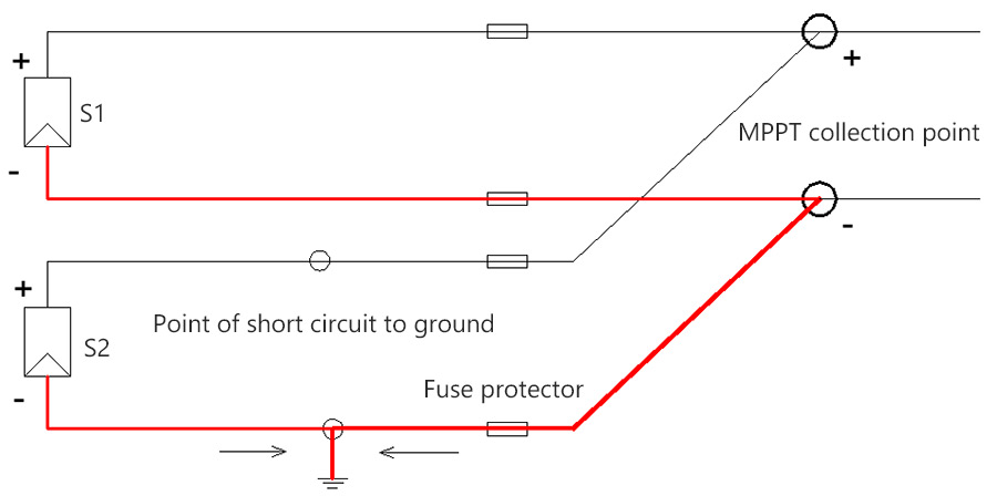
As shown in the figure above, one MPPT is connected to two loops of components, which are respectively S1 and S2. When a short circuit to ground occurs in some place in S2, it can be seen from the figure that the negative current of S2 does not flow to the grounding point through the fuse, and the negative current of S1 flows to the grounding point through the public convergence point and S2 fuse protector. The total current of the fuse does not exceed 15% of the rated current, it fails below the fusing condition. It will not cause any fire risk, so the fuse protector is not required.
When a MPPT is configured with N (N ≥ 3) strings, the short circuit will be increased.
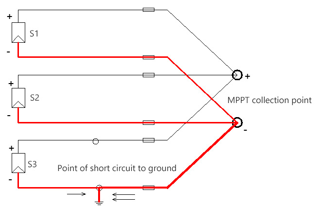
As shown in the figure above, one MPPT is connected to three loops of components, which are respectively S1, S2 and S3. When a grounding short circuit occurs somewhere in S3, it can be seen from the figure that the negative current of S3 does not flow to the grounding point through the fuse, and the negative current of S1 and S2 flows to the grounding point through the public convergence point and S3 fuse protector. The total current of the fuse is 2 times of the short-circuit current, and it reaches the fusing condition. There will be the fire risk. Therefore, the multiple strings should be configured with the fuse protector for protection.
Combining with the practical and scientific design, according to different terrain and component sheltering situations, the power inverters with different MPPT architectures shall be selected, so as to reduce the procurement cost and maintenance cost, and improve the economic efficiency of the power station.
1. On flat areas with no sheltering and good lighting conditions, it is recommended to select the power inverter with single-loop MPPT and single-stage structure to improve system reliability and reduce system cost like solar inverter with MPPT charge controller on inverter.com.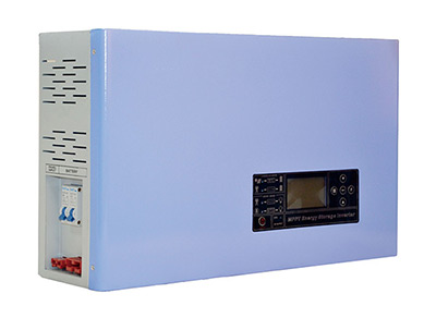
- 700W to 6kW solar inverter with MPPT charge controller
- Voltage of DC input/ AC output can be customized
- Selectable 30A/ 60A battery max charge current
- The maximum conversion efficiency is 98%
- (DC) battery preferred mode
- (AC) commercial power preferred mode
- Powerful protection functon
2. As to the mountainous power stations with complicated terrains, such as the large-scale power station of pacemaker base, there are phenomena of inconsistent orientation and partial sheltering, and different mountains have different sheltering characteristics, which will cause the component mismatch problem. Then, it is required to select the multiple-loop MPPT, then the power inverter with 2 string inputs for each MPPT loop is a better choice, which has no fuse wearing part, high fault positioning accuracy and easy maintenance.
3. As to the mountainous power stations and roof power stations with no complicated terrains, there is no component sheltering, it is suggested to choose one MPPT to configure the power inverter with several strings, so as to take into account both string mismatch and high efficiency. Its design is more flexible.