-
You have no items in your shopping cart.
- Register
- Log in
- Wishlist
- Shopping cart

Frequency Inverter Solution
A frequency inverter — also called a variable frequency drive (VFD) or adjustable speed drive (ASD) — controls the speed and torque of an AC motor by converting fixed-frequency mains power into a variable-frequency, variable-voltage output. Because motor speed is directly proportional to supply frequency, a VFD can slow a pump, fan, or conveyor to exactly the speed the process requires rather than running it flat-out and throttling the output mechanically.
The energy impact is dramatic: reducing motor speed by 20 % cuts power consumption by nearly 50 %, thanks to the cube-law relationship between speed and power in centrifugal loads. For industrial and commercial operators, this means measurable electricity savings, lower maintenance costs, and longer equipment life — all from a single device installed between the mains supply and the motor.
inverter.com supplies single-phase, single-to-three-phase, and three-phase VFDs covering 0.4 kW to 400 kW. The five application scenarios below illustrate how these products solve real-world problems across different industries.

Industry-Specific Scenario Solutions: Table of Contents
- 🔴Scenario 1 — Building & Construction: Hoist Speed Control
- 🔴Scenario 2 — HVAC: Fan & Pump Variable-Speed Control
- 🔴Scenario 3 — Water & Wastewater: Constant-Pressure Pump Control
- 🔴Scenario 4 — Food & Beverage Processing: Conveyor Belt Speed Control
- 🔴Scenario 5 — Small Workshops: Single-Phase to Three-Phase Conversion
- 🔴Frequently Asked Questions about Frequency Inverters
Inverter.com products for use:
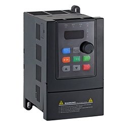 |
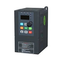 |
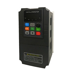 |
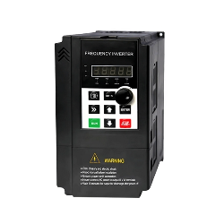 |
| Single Phase Frequency Inverter | Single to Three Phase Frequency Inverter | 3 Phase Frequency Inverter | 120V Input Frequency Inverter |
🔴Scenario 1 — Building & Construction: Hoist Speed Control
Background
High-rise construction projects depend on personnel and material hoists to move workers and supplies between floors throughout the workday. Traditional hoist systems use direct-on-line or star-delta starters, which slam the motor from zero to full speed in a fraction of a second. The resulting mechanical shock strains the gearbox, rack, and braking disc, while the electrical inrush — often 6–8 × rated current — stresses cables and contactors.
Challenges
- Hard starts cause excessive wear on rack-and-pinion gearing and brake pads, increasing downtime.
- Direct braking from full speed creates a jolt that can dislodge loose materials and poses a safety risk to passengers.
- Single-speed operation wastes energy during light-load lifts.
- Inrush current forces the site to oversize the cable supply and distribution board.
Recommended Solution
| ⚡ Challenge | 🔧 Solution | ✅ Result |
| Hard starts damage gearing. | Install a three-phase VFD rated for hoist duty. | Smooth acceleration from 0 → operating speed. |
| Brake shock risks safety. | Enable soft-start / soft-stop ramp. | Controlled deceleration eliminates jolt. |
| Inrush current oversizes wiring. | Activate built-in overload & over-voltage protection. | Cable size reduced vs. DOL starter. |
A three-phase frequency inverter from inverter.com replaces the contactor-relay control panel. The VFD ramps motor frequency from 0 Hz to 50/60 Hz over a configurable time (typically 5–15 seconds for a loaded cage), so acceleration is smooth and jolt-free. The same ramp-down profile governs braking: frequency decreases progressively until the mechanical brake engages at near-zero speed, eliminating the "car-sliding" phenomenon.
Built-in protections — over-current, over-voltage, under-voltage, phase-loss, inverter over-temperature, and motor overload — replace multiple discrete relays. The VFD's current-limiting function reduces inrush to roughly 1.5 × rated current, allowing the supply cable to be downsized compared with a DOL installation.
Expected Outcomes
- Energy savings of 15–30 % per lift cycle versus fixed-speed operation.
- Gear and brake disc life extended by 30–50 % due to elimination of shock loading.
- Electrical supply cable cross-section reduced, lowering installation cost.
- Compliance with modern site safety requirements for smooth passenger hoist operation.
🔴Scenario 2 — HVAC: Fan & Pump Variable-Speed Control
Background
Commercial and industrial HVAC systems consume 30–50 % of a typical building's electricity. Chilled-water pumps, cooling tower fans, and air-handling unit fans are the primary energy loads. In most legacy installations, these motors run at fixed speed, and airflow or water flow is controlled by dampers or throttle valves — essentially wasting energy to restrict output from a motor running flat-out.
Challenges
- Throttle valves and dampers dissipate energy as pressure drop rather than saving it at the motor.
- Fixed-speed fans cannot match varying cooling demand throughout the day, leading to over-cooling and under-cooling.
- Frequent DOL starts shorten motor winding life in systems that cycle on/off.
Recommended Solution
| ⚡ Challenge | 🔧 Solution | ✅ Result |
| Throttling wastes energy. | Replace throttle with VFD speed control. | Energy use falls 30–50 %. |
| Fixed speed can't match the load. | Use a building management system (BMS) 4–20 mA signal to set speed. | Supply temperature held ± 0.5 °C. |
| Repeated starts degrade windings. | Soft-start on every restart. | Motor life extended significantly. |
A three-phase VFD installed on the pump or fan motor accepts a 4–20 mA analog signal from the BMS and modulates motor speed in real time to match the building's actual cooling or heating demand. At 80 % of rated speed, the motor draws only about 51 % of full-load power; at 60 % speed, just 22 %. For a 15 kW cooling tower fan operating 8 hours/day, this translates to energy savings of USD 800–1,500 per year at typical US commercial electricity rates.
For single-phase supply buildings — common in light commercial premises — a single-to-three-phase VFD (inverter.com/single-phase-to-three-phase-inverter) allows the installation of an efficient three-phase motor where only a single-phase supply is available, combining energy efficiency with supply flexibility.
Expected Outcomes
- 30–50 % reduction in HVAC fan and pump electricity consumption.
- Improved indoor climate control with real-time speed matching to load.
- Motor winding life extended through elimination of direct-on-line starts.
- Payback period typically 12–24 months on new VFD installation.
🔴Scenario 3 — Water & Wastewater: Constant-Pressure Pump Control
Background
Municipal water distribution systems and industrial process water networks must maintain constant delivery pressure as demand fluctuates throughout the day — peak demand at 7 a.m. and 6 p.m., near-zero demand at 3 a.m. Fixed-speed pump sets handle this by switching pumps on and off, causing pressure spikes and water hammer, and running pumps at full power even when delivering a fraction of rated flow.
Challenges
- Pressure surges from pump start/stop cycles cause fatigue at pipe joints and accelerate valve wear.
- Water hammer can rupture fittings and damage flow meters.
- Running pumps at full power during low-demand periods wastes electricity.
- Frequent motor starts raise maintenance frequency and reduce motor life.
Recommended Solution
| ⚡ Challenge | 🔧 Solution | ✅ Result |
| Pressure surges damage pipes. | A PID-controlled VFD modulates pump speed to maintain the set-point pressure. | Pressure held ±2 % of set point. |
| Full-power operation at low flow. | The pressure transducer provides a 4–20 mA signal to the VFD. | Energy savings 25–45 %. |
| Frequent starts wear out motors. | Speed ramps eliminate water hammer. | Motor starts reduced to <5/day. |
A three-phase frequency inverter with a built-in PID controller closes the loop between a pressure transducer on the discharge header and the pump motor speed. When downstream demand drops, the VFD slows the pump; when demand rises, it accelerates—maintaining header pressure within a tight band without valve throttling. The gradual speed ramp also eliminates water hammer.
Expected Outcomes
- Pressure variation reduced to ±2 % of set point versus ±15–25 % with on/off control.
- Electricity consumption reduced by 25–45 % depending on demand profile.
- Pipe and fitting fatigue failure rate reduced significantly.
- VFD payback typically 18–30 months in municipal water applications.
🔴Scenario 4 — Food & Beverage Processing: Conveyor Belt Speed Control
Background
Bottling lines, bakery conveyor systems, and packaging machines must synchronize belt speed with upstream and downstream equipment. Traditionally, this is done with mechanical gearboxes and clutches — expensive to maintain and inflexible when production rates change. A VFD-driven conveyor eliminates the gearbox and allows speed changes from the operator panel or a PLC in seconds.
Challenges
- Mechanical gearboxes require lubrication, wear, and periodic replacement.
- Production line changeovers require physical gear changes or belt-and-pulley swaps.
- Sudden motor starts can jam products or spill liquids on filling lines.
Recommended Solution
| ⚡ Challenge | 🔧 Solution | ✅ Result |
| Gearbox wear & maintenance costs. | Single-phase or three-phase VFD drives the conveyor motor directly. | Gearbox eliminated. |
| Slow production changeover. | Speed set via operator HMI or PLC analog output. | Speed change in <5 seconds from HMI. |
| Hard starts jam or spill product. | Configurable ramp time 0.5–30s. | Smooth start prevents product spillage. |
For light conveyor applications on single-phase supply (up to 2.2 kW), a single-phase output VFD drives a standard single-phase motor directly. Heavier-duty multi-zone conveyor systems typically use a three-phase VFD per zone, each receiving a speed reference from the plant PLC via a 0–10 V analog signal, enabling electronic line synchronization without any mechanical coupling.
Expected Outcomes
- Gearbox eliminated, saving USD 500–3,000 per drive point in maintenance.
- Production line speed changeover time reduced from hours to seconds.
- Product spillage and jamming incidents reduced on filling and portioning lines.
- Energy savings of 10–25 % versus fixed-speed gearbox drives at partial throughput.
🔴Scenario 5 — Small Workshops: Single-Phase to Three-Phase Conversion
Background
Lathes, milling machines, drill presses, and bench grinders designed for three-phase 380 V supply are far more energy-efficient and torque-smooth than their single-phase equivalents — but many small workshops and garages in residential or rural areas have only a 120 V or 240 V single-phase supply. A rotary phase converter is the traditional workaround, but it is bulky, noisy, and expensive. A single-to-three-phase VFD solves the same problem in a compact, quiet, and controllable package.
Challenges
- Three-phase machines are unavailable to workshops with only single-phase supply.
- Rotary phase converters are loud, large, and produce poor-quality synthetic third phase.
- Fixed-speed machine tools cannot be slowed for finishing cuts or tool changes.
Recommended Solution
| ⚡ Challenge | 🔧 Solution | ✅ Result |
| No three-phase supply available. | Single-to-three-phase VFD converts 1-phase 120/240 V to 3-phase 0–415 V. | Any three-phase machine tool runs on single-phase supply. |
| Rotary converter is bulky & noisy. | Output frequency 0–400 Hz gives a full speed range. | Variable spindle speed from a panel knob. |
| Fixed spindle speed limits versatility. | Compact wall-mount installation. | Quiet solid-state operation. |
A single-to-three-phase VFD from inverter.com accepts 120 V or 240 V single-phase input and synthesizes a balanced three-phase output. Output voltage and frequency are both variable, so the machinist can dial in spindle speed from the front panel without changing belt pulleys. The 120V input models are particularly useful in North American workshops where 240 V single-phase is not always available at the machine location.
Expected Outcomes
- Full range of industrial three-phase machine tools accessible from single-phase supply.
- Spindle speed continuously variable 0–100 % from front panel.
- Noise level far below rotary converter (solid-state operation).
- Installation space reduced by 60–80 % vs. rotary converter + starter panel.
🔴Frequently Asked Questions about Frequency Inverters
- Q1: What is the difference between a frequency inverter, a VFD, and an ASD?
All three terms describe the same device. "Frequency inverter" is common in European and Asian markets; "variable frequency drive (VFD)" is the standard North American term; "adjustable speed drive (ASD)" is used in some IEEE standards. They all convert fixed-frequency AC mains power into variable-frequency, variable-voltage AC output to control motor speed. - Q2: Can I use a single-phase VFD to run a three-phase motor?
Yes — this is exactly what a single-to-three-phase frequency inverter does. The device accepts single-phase 120 V or 240 V input and produces three-phase output at the voltage and frequency you set. The three-phase motor then runs normally. The VFD input current will be higher than the motor nameplate current, so the supply circuit must be sized accordingly. - Q3: How much energy can a VFD save on a pump or fan?
Savings depend on how much the speed is reduced from full speed. The relationship follows the affinity laws: power varies with the cube of speed. Reducing a centrifugal pump or fan to 80 % of full speed saves approximately 49 % of the energy; reducing to 60 % of full speed saves approximately 78 %. Real-world savings are typically 20–50 % depending on the load profile. - Q4: Do I need special wiring between the VFD and the motor?
VFDs produce a pulse-width-modulated (PWM) output that can cause higher cable capacitance effects over long cable runs. For runs exceeding 30 meters (100 feet), it is good practice to use VFD-rated cable (shielded, low-capacitance) and, if required by the VFD manufacturer, an output line reactor to reduce dV/dt stress on motor windings.
