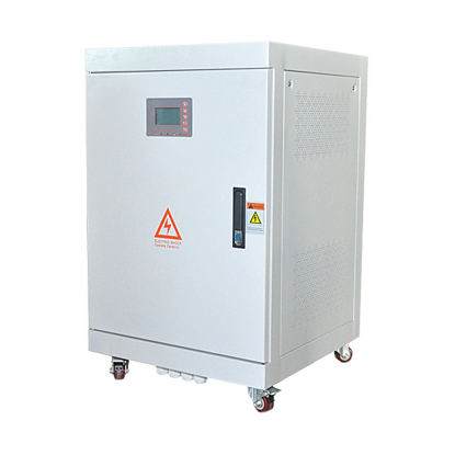
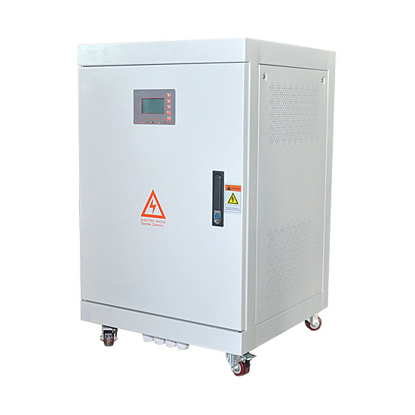
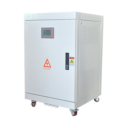
10kW Pure Sine Wave Off Grid Solar Inverter
Buy low price three phase 10kw pure sine wave off grid inverter for without battery backup system, it converts 96V/ 120V DC to 220V/ 380V/ 480V AC, with powerful protection function, LCD display, more reliable and safe.
-
*
-
-
*
-
-
*
-
-
*
-
-
*
-
10kW off grid no baterry inverter for solar power system, with strong load capacity, good transient response, 230V/ 240V/ 400V AC stable output voltage, pure sine wave full power output, low waveform distortion.
Features
- Two kinds of start mode: Step-down voltage start and variable frequency start. Customers can set start mode according to the type of their load.
- The output voltage can be set between -40 % to +20 % of rated voltage. And the output voltage is very accuracy ±1%.
- Pure sine wave output. With good dynamic response less than 50MS, waveform distortion rate smaller, higher conversion efficiency and stable output voltage.
- Adopts black pure aluminum radiator, which confirms the best radiating performance.
- Powerful data display function. LCD can display the DC input voltage, output frequency, phase voltage, phase current, AC bypass input voltage, power consumption (kWH), time and date, temperature, fault code display.
- Wide input voltage can work without battery and solar charge controller, save more cost and with MPPT wide voltage input function, maximum use of solar power.
Parameter List
Model |
ATO-OGI-10kW |
Size (D*W*H) |
450*550*760mm |
Weight |
145kg |
Certificate |
CE, UL, SA, SAA, VDE |
Warranty period |
12 months |
AC Input |
Rated voltage |
AC input voltage is the same value as the AC output |
DC Input |
Rated voltage |
96V/ 108V/ 120V/ 192V DC (can be customized) |
Rated current |
52A @192V DC |
AC Output |
Rated output power |
10kW |
Output waveform |
Pure sine wave |
Rated voltage |
208V/ 220V/ 230V/ 240V/ 380V/ 400V/ 415V/ 460V/ 480V (optional) |
Phase |
3 phase 4 wire+PE wire (single phase/ split phase can be customized, please contact us by email) |
Rated phase current |
15A @380V AC |
Frequency |
50Hz or 60Hz |
Power factor |
>0.99 |
Overload ability |
150%, 5 seconds |
Efficiency |
>93% |
Waveform distortion rate |
THD<3% |
Dynamic response (0 to 100% load) |
5%, ≤50ms |
Display |
LCD |
Running mode |
Working continously |
Electrical insulation properties |
2000Vac, 1min |
Communication interface |
RS485 (optional), it can remote control the start/stop of the inverter and convey the data as below: 1. Input DC current 2. Input DC voltage 3. Output AC current 4. Output AC voltage 5. Power consumption (kWH) 6. Some fault information |
Protection Function |
Protection |
Input reverse polarity, under voltage, over-voltage, output over-current, short circuit, overheating |
Colling method |
Fan-cooled |
Short-circuit protection |
No automatic recovery, need to restart the machine |
Working Environment |
Noise (1 meter) |
≤50dB |
Degree of protection |
IP20 (indoor) |
Working altitude |
≤2000m |
Working temperature |
-25~+55℃ |
Relative humidty |
0~90%, non-condensing |
Note |
The above parameters are for reference only, can be customized according to customer's requirement! |
Tips:
The photovoltaic off-grid system has no uniform specification and it must be designed according to the user demand. The model selection and calculation of components, inverters, controllers, batteries, cables, switches and other equipment are mainly considered. Before the design, in order to do a good job in the preliminary work, it is required to understand the user's load type and power, the climatic condition of the installation site and the electricity consumption of the user. After making clear the demand, the scheme can be well compiled.
1. The voltage of the component and the voltage of the battery should be matched. The PWM controller solar module and the storage battery are connected by an electronic switch, without an inductance equipment in the middle. The voltage of the component is between 1.2 and 2.0 times the voltage of the battery. If the battery has a voltage of 24V, the input voltage of the component is within 30-50V. The MPPT controller has a power switch tube and an inductor circuit in the middle. The voltage of the component is about1.2-3.5 times of the voltage of the battery. If the battery has a voltage of 24V, the component input voltage is within 30-90V.
2. The output power of the component must approach to that of the controller. For example, in case of a 48V 30A controller with an output power of 1440VA, the power of the component should be around 1500W. In selecting the controller, please firstly check the voltage of the battery, and then divide the component power by the voltage of the battery, which is exactly the output current of the controller.
3. If the power of one inverter is insufficient, multiple inverters must be connected in parallel. The output of the photovoltaic off-grid system is connected to the load. The voltage, current phase and amplitude of each inverter output terminal are different. If the inverter is connected in parallel with the output terminal, it is required to add an inverter with the parallel operation function.
Read more related blog: PV Off-Grid Solar System Troubleshooting