Today we'll introduce how to make a power inverter. This homemade inverter has simple circuit, low cost, easy maintain, and high efficiency. And it can be made by anyone who has a little practical ability. Although this DIY inverter does not have the same high-end and complex switching power supply integrated circuit as high-quality power inverters on the market, as well as field effect power amplification, its effectiveness is not inferior to others.
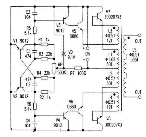
This power inverter is quasi-sine wave output with no-load current less than 450 mA, load capacity more than 300W and efficiency more than 85%. It can power the fan, bulb, electric iron or a small TV in series with a 100W bulb (due to the degaussing coil, the starting current is too large, so it is necessary to start up in series with a bulb. If the degaussing coil is removed, the bulb is not necessary to connect in series). It brings great convenience to life and maintenance. Even if there is a fault, it will not cause voltage rise and burn out household appliances. The circuit of this DIY power inverter is shown in the following figure.
Working principle of this homemade inverter
After the 12V DC power is connected, the multi-vibrator that is composed of V1, V2, R1-R4, C1 and C2 starts oscillation, and the collector of V1 and V2 takes turns to output about 50Hz of square wave with positive polarity. When the integral circuit composed of C3 and R5, C4 and R6 integrates into quasi-sine wave, and then V5 and V6 are excited respectively by phrase inversion and amplification of V3 and V4, the power transistors of V7 and V8 in the last stage take turns to turn on and cut off, and their collector current induce about 50 Hz quasi-sine high voltage output at the high voltage side of the transformer while flowing through the primary winding L1 and L2 of the transformer.
Choosing the components for the inverter
Most of components of this power inverter can be removed from scrap circuit boards. Among them, V5 and V6 are made with D880 or C2073, while V7 and V8 are made by three of 3DD207 in parallel with parameters of 200V/5A/50W, which can also be replaced by 3DDl5D. As for adjustable resistance RP, it can be removed from the tailboard of old color TV set, and other resistors and capacitors have no special requirements. The coils Ll and L2 are enameled wires of Φ1.62mm, each winding 50 turns, L3, L4 and L5 are all enameled wires of Φ 0.53mm with windings of 12, 12 and 945, respectively. In terms of power tube, it should be equipped with as large a radiator as possible, and the device is equipped with a radiator of 150cm wide. With regard to transformer core, it should have an effective cross-sectional area of more than 20 cm², and you can use the charger core of scrap storage battery large enough or the annular power transformer core on the amplifier.
Making and debugging the inverter
After installing all the power tubes with radiators, all the other components are welded on the power tubes by lap welding without making circuit boards. Since V1, V2 and components that make up the oscillating circuit may cause inconsistencies in the amplitudes of oscillating signals from collectors of V1 and V2, as well as excessive consumption for nothing due to characteristic difference, adjustable resistance RP is used to adjust the balance of oscillating circuit. The regulation circuit composed of VD and R7 is a necessary part to ensure the stable operation of oscillating circuit, which can solve the problem of unbalanced oscillating circuit caused by the voltage drop of storage battery.
When debugging the power inverter, first switch RW to the middle position, set the ammeter in series at the 12V power supply terminal, turn on with no load and adjust the RP to minimize the current. Then, connect 60W bulb at the load terminal, electrify and adjust RP to minimize the current. Repeat no-load adjustments for many times until the current can no longer be adjusted. At this time, the noise should be minimal when listening to the sound close to the transformer. If the balance is not adjusted, the noise will be so loud that you can hear it without pressing your ear close to it. The emitters of V5 and V6 are inversely connected with the base poles of V7 and V8 by winding L3 and L4 respectively, which can deepen the depth of V7 and V8 saturation and cut-off, and improve the efficiency of V7 and V8. Please attention that, the phase of L3 and L4 should be correct, if not, the output voltage will not be high with poor load capacity, even if there will be voltage output on the high voltage terminal. After debugging, you can find a scrap computer power box to put the whole device in it and use its fan to abstract heat.