With advances in solar photovoltaic technology, many technical terms, in addition to solar power generation systems, PV sunshine rooms, PV greenhouses, and other civilian projects, have taken a deep root in residents' life. For instance, many purchasers ask questions when buying an inverter, for example, how many circuits of MPPT does this inverter has? What the power-generation efficiency is like?
Although many people are aware of the MPPT function, they are unclear about the circuit's working principles. This paper will briefly introduce the DC-DC conversion circuit, a vital component of MPPT.
MPPT is the abbreviation of Maximum Power Point Tracking. As a vital function of the solar inverter, MPPT not only effectively raises the radiation utilization rate and maximizes the solar inverter's working efficiency but also converts voltage and currents output by modules to adjust their power according to sunlight intensity. When sunlight remains dim, MPPT is likely to raise modules' input voltages to track the maximum power of solar inverters. Take the most commonly used Boost conversion circuit as an example, the following brief analysis is made:
Boost is generally explained as lifting, raising, and pushing upwardly. In fact, it also means raising the voltage. In the following part, we will analyze how it converts voltages.
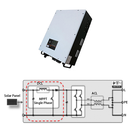
Internal circuit schematic diagram of single-phase inverter
The figure listed above presents a topological structure commonly used by single cameras. Here the red block diagram is separated out for further analysis.
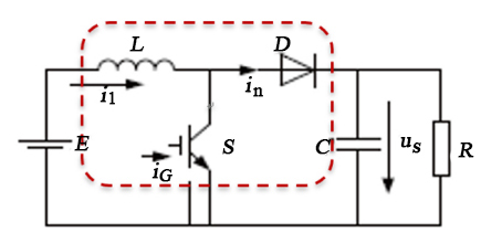
It can be easily seen from the diagram that the Boost consists of three elements, including inductance, switching tube, and dioxide. The following part will briefly analyze its working modes.
Working Mode 1: Switch tube S is on
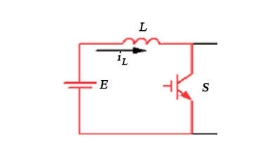
Direct current E is applied to inductance. The power supply E is under conductive charging. Ton is the conduction time for switching tubes; the inductance voltage is equal to E.
Working Mode 2: Switch tube S is disconnected
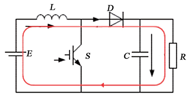
DC power supply E and energy saved by inductance are converted to charge capacitance C through diode D till U0. Similarly, we assume the time for disconnecting the switching tube S is Toff. According to Kirchhoff's law, the voltage on the inductance is UL=U0-E.
As is known to all, the current of inductance in a stable state doesn't mutate (as stipulated by the Law of Volt-Second Balance). In other words, the increase in current when the switch is connected equals the decrease when the switch is disconnected. This relationship can be described by the following formula:
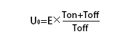
E × Ton = (U0-E) × Toff
The above formula can be transformed as follows:
Duty ratio D is introduced. When the switch is connected, the ratio is D. when the switch is disconnected, the ratio is 1-D. The formula listed above can be rewritten as follows:
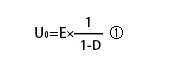
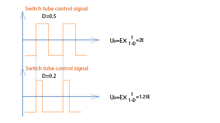
As is shown by Formula ①, the output voltage is U0>E, namely Boost raises the voltage. Suppose an appropriate duty ratio signal is given to switching tube S, the output voltage can be adjusted to work out the desired voltage value and expand the output voltage.
Of course, the duty ratio is not selected randomly but takes various design factors into consideration. These factors are not discussed in detail. In conclusion, the DC-DC converter, as a core circuit for achieving the MPPT function, has been widely applied to solar on-grid inverters, light charging, and light saving to considerably raise the efficiency of utilizing PV power. In particular, DC-DC also gives birth to Buck-Boost, CUK, and other characteristic conversion circuits in actual application, which greatly cater to people's special needs.