Solar charge controller, also known as solar charge and discharge controller, is an automatic control device used in solar power generation systems to control the charging of batteries by multiple solar cell arrays and the power supply of batteries to solar inverter loads. The installation procedure of a solar charge controller needs to follow certain steps and precautions. The following is a clear installation guide.
Installing a solar charge controller
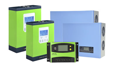
Required Materials and Tools: Solar Charge Controller, Solar Panel, Battery, DC Load (optional), Wires and Connectors, Screwdriver, Wire Cutter/Stripper, Multimeter
- Solar charge controllers should be installed in a well-ventilated area, away from direct sunlight, high temperature, and should not be installed where water can penetrate the solar controller. Place the charge controller close to the battery to minimize voltage drop, ensuring easy monitoring and maintenance.
- Select the appropriate screws to mount the solar controller on the wall or other platform, the screws should be M4 or M5, and the nut diameter should be less than 10mm. Mount the Charge Controller Use the screws or other mounting hardware provided with the device to securely mount the charge controller on a stable surface.
- Please leave enough space between the wall and the solar controller to facilitate the cooling and connection sequence.
- Locate the battery terminals on the charge controller, usually marked "BAT" or with a battery symbol. Connect the battery to the controller using wires of appropriate gauge. Make sure the polarity is correct (positive to positive, negative to negative).
- Connect securely to prevent any loose connections. Use a multimeter to make sure the battery voltage is within the expected range.
- Find the load terminals on the charge controller, usually marked "LOAD" or with a light bulb symbol. If you have any DC appliances or devices powered directly by the solar system, connect the DC load to these terminals. Make sure the load does not exceed the current rating of the solar charge controller load output.
- Double-check all connections to make sure they are correct and secure, and make sure there are no short circuits or reverse polarity.
- The mounting hole spacing is 20-30A (178*178mm), 40A (80*185mm), 50-60A (98*178mm), and the mounting hole diameter is 5mm.
- All terminals are connected tightly when packaged, please loosen all terminals for better connection. To avoid short circuit, screw the battery pack to the controller first, then connect the solar panel, and then connect the load.
- If the controller terminals are short-circuited, it will cause fire or leakage, and you must be very careful. (We strongly recommend connecting the fuse on the battery pack side to 1.5 times the rated current of the controller), after the correct connection is successful. When there is sufficient sunlight, the LCD will display the solar panel, and the arrow from the solar panel to the battery pack will light up.
Solar controller wiring method
- Battery connection
Before connecting the battery, make sure the battery voltage is more than 6V to start the controller. If the system is 24V, make sure the battery voltage is not less than 18V. The system voltage selection is only automatically recognized when the controller is started for the first time.
When installing the insurance, pay attention to the maximum distance of 150mm between the insurance device and the positive terminal of the battery, and turn on the insurance after determining the correct wiring.
Warning: A short circuit in the positive and negative battery terminals and the wires connected to the positive and negative terminals can cause a fire or explosion hazard! Please be sure to operate carefully!
2. Load connection
The load side of the solar charge controller can be connected to a DC power device with the same rated operating voltage as the rated voltage of the battery, and the controller supplies power to the load with the battery voltage.
Connect the positive and negative terminals of the load to the load terminals of the controller. There may be voltage at the load terminal, so the wiring should be done carefully to avoid short circuits from time to time.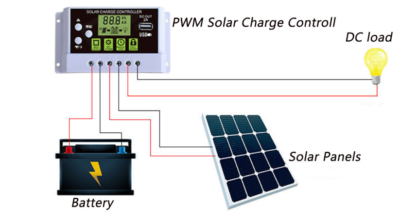
A fuse should be connected to the load anode or cathode wire, and the fuse should not be turned on during installation. After the installation, the correctness of the fuse should be determined.
If the load is connected through the switchboard, each load circuit has a separate connection insurance, all the load current can not exceed the rated current of the controller.
3. PV array connection
The solar charge controller can be used for off-grid solar modules of 12V and 24V, and also for grid-connected modules where the open-circuit voltage does not exceed the specified maximum input voltage. The solar module voltage in the system should not be the minimum system voltage.
Warning: Electric shock is dangerous! Photovoltaic arrays may generate very high voltages, so be careful when wiring to prevent electric shock.
4. Check after installation
Check all the connections again to see if the positive and negative terminals of each terminal are correct and if all 6 terminals are tightened.
5. Power on to confirm
When the battery supplies power to the controller, the battery LED indicator on the controller will light up when the controller is started, so pay attention to observe whether it is correct.
Solar controller installation tips
Wiring order: First to the battery, then to the solar panel, and finally to the load.
Tip: Be sure to strictly comply with the prescribed wiring order. Due to the confusing order, some controllers may not be able to automatically identify the 12V/24V/48V system, thus making the controller unable to operate normally.
It is better to string a fuse into the battery pack to ensure that the battery will not be short-circuited, otherwise it will cause serious consequences. The specification of the fuse must be 2~3 times the rated current.
The solar controller should be installed in a dry environment. Even if the controller is completely waterproof, it is best not to be buried in the soil.