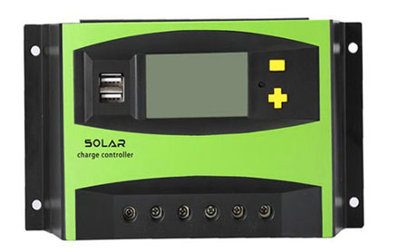
The solar controller can also be said to be a solar charge controller. It is a controller with two charging modes, one is MPPT charging mode, and the other is PWM charging mode. PWM controller, with battery charging and discharging management function, can prevent the battery from overcharging and over-discharging. Now Inverter.com will explain to you the PWM charging mode.
PWM controller basic
The solar charging controller's PWM (pulse width modulation) charging mode is an efficient charging method. It controls the analog circuit through the digital output of the microprocessor to realize the digital encoding of the analog signal level. The early photovoltaic controllers were all PWM. The electrical structure was simple. The controller consisted of a main power switch, a capacitor, and a drive and protection circuit. The output voltage was controlled by the switch tube's PWM duty cycle.
There is only one PWM controller switch between the solar array and the battery panel. As the battery is gradually filled and the battery voltage rises, the PWM of the solar charge controller will gradually reduce the power provided to the battery. The photovoltaic output will be output according to the maximum power.
Since there is only one switch connected between the solar module and the storage battery of the PWM type controller, and there is no inductive voltage divider in the middle, the voltage of the module is about 1.2-2.0 times the voltage of the battery when designing, such as a 24V battery, the input of the component The voltage is between 30-50V, and each string can only be equipped with one module. For a 48V battery, the input voltage of the module is between 60-80V, and each string can only be equipped with two modules.
Principle of PWM Controller
The principle of the PWM controller is based on the fact that narrow pulses with equal impulse but different shapes have the same effect when applied to the link with inertia. PWM control principle: divide the waveform into 6 equal parts, which can be equivalently replaced by these 6 square waves. There are many classification methods of pulse width modulation, such as single polarity and bipolarity, synchronous and asynchronous, rectangular wave modulation and sine wave modulation, and so on.
Unipolar PWM control means that the carrier only changes in one direction within half a period, and the resulting PWM waveform only changes in one direction. The bipolar PWM control method is the opposite of the unipolar one, which changes the carrier in two directions within half a cycle.
According to whether the carrier signal is synchronized with the modulation signal, PWM control can be divided into synchronous modulation and asynchronous modulation. The characteristic of rectangular wave pulse width modulation is that the output pulse width columns are of equal width, and can only control harmonics of a certain order; The output waveform is close to a sine wave. Sine wave pulse width modulation is also called SPWM. Generating pulse width according to the control signal is the key to this technology. At present, the triangular wave comparison method, the hysteresis comparison method, and the space voltage vector method are commonly used.
Triangle wave comparison method
Principle:
The triangle wave comparison method is also called carrier modulation method or unipolar PWM. Its basic principle is to compare the reference signal (usually a sine wave) with a high-frequency triangle wave. When the reference signal is greater than the triangle wave, the output is high; when the reference signal is less than the triangle wave, the output is low.
Features:
- Simple implementation, easy to understand and implement.
- There are many harmonic components, especially near the switching frequency.
- Applicable to single-phase and three-phase inverters.
Application:
Widely used in single-phase inverters and simple motor control systems.
Hysteresis comparison method
Principle:
The hysteresis comparison method is an adaptive PWM technology. It compares the actual output current with the reference current. When the actual current exceeds the set hysteresis band, the switch state is changed to maintain the current within the hysteresis band.
Features:
- Fast response speed, can better suppress current fluctuations.
- The switching frequency is not fixed, depending on the load conditions and the set hysteresis bandwidth.
- The implementation is relatively complex, and the hysteresis band needs to be accurately designed.
Application:
Commonly used in high-performance motor control, such as current control of DC motors and permanent magnet synchronous motors (PMSM).
Space voltage vector method
Principle:
The space voltage vector method is a PWM method based on vector control theory. It generates an approximate output voltage vector by calculating the position of the reference voltage vector in the hexagonal space and selecting the appropriate switch state combination.
Features:
- Provides higher DC bus utilization (about 15% improvement).
- The output voltage has fewer harmonics and better waveform quality.
- The implementation is more complex and requires a lot of calculations.
Application:
Widely used in three-phase inverters, high-performance motor drive systems, and other high-demand power electronic equipment.
These three methods have their own advantages, and the specific choice depends on the application requirements and system design requirements. In practical applications, it is often necessary to weigh multiple aspects such as implementation difficulty, switching frequency, harmonic characteristics, and system performance.
There are many high efficiency solar charge controllers at Inverter.com, including 10 Amp, 20 Amp,...60 Amp PWM solar charge controllers, and 20A, 30A to 60A MPPT solar charge controllers. If you want to get more information about solar charge controllers, please click inverter shop.