The solar energy charge controller is an automatic control device controlling the solar battery array to charge the battery and the battery supplies power to the solar inverter load in the photovoltaic power generation system. It can set the control conditions according to the charging and discharging characteristics of the battery, so as to control the power output of the solar energy battery component and battery to the load. Its main function is to protect the battery and stabilize the working state of the power station. The photovoltaic solar controller can be divided into a switch type controller, a pulse width modulation (PWM) type charge controller, a maximum power point tracing (MPPT) charge controller, and an intelligent controller according to functions and circuit structures.
Switch type controller
The main function of the general charging and discharging controller is to restrict the charging current and voltage, so as to ensure that the battery can be quickly and effectively charged and discharged, thus protecting the battery and avoiding overcharging and over-discharging. In addition to the functions of the usual controllers, the photovoltaic charging and discharging controller must also take into account the volt-ampere characteristics of photovoltaic modules in power generating. The early photovoltaic controllers are relatively simple and usually adopt the single-stage control method. In other words, the so-called controller is to set one electronic switch between the photovoltaic component and battery as shown in figure 1. When the battery reaches the set voltage, the switch is cut off and the charging stops. When the voltage drops, the charging is restarted. Such a process repeats until the battery is charged fully. Due to the influence of the floating charging voltage during the charging process of the battery itself, it frequently charges and stops in the rear period of this charging mode, and it requires a rather long time, However, for solar power generation, the time of sunshine during the day is limited, so the battery is often not fully charged. At the same time, when there is a sun in the daytime, the power generated by the photovoltaic is greatly wasted and the efficiency is rather low. It is usually used in small power generation systems below 100W.
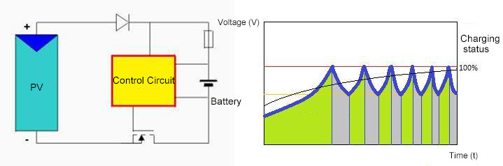 Figure 1: Switch type controller working mode
As to the switch-type charge controller, the output of the PV module is directly connected to the two ends of the battery through the control switch, therefore, the output voltage of the PV module must be designed strictly according to the battery voltage. If it is too low, it cannot be charged normally. If it is too high, it will cause waste or even damage the solar charge controller and battery. The battery voltage has a close relationship to the charging state of the battery. For example, a 12V battery has a voltage of about 11V in a deficient state, in a fully charged status, it approaches 15V. For such a battery, our input voltage must be greater than 15V. Combined with the voltage declining factor of the PV module because of the temperature influence, the design voltage of the PV module is usually 17-18V. Obviously, in the early stage of charging a depleted battery, the output voltage of the PV module will be clamped to a lower range by the battery, and the efficiency is very low. When the battery is almost fully charged, the battery will enter the floating charge state, that is, the charging and stopping state. When the battery is in the floating charge, the electricity generated by the PV is wasted, and the battery is not fully charged at this moment. Such a photovoltaic solar charge controller is simple and inexpensive. However, the electricity generated by the PV module is not fully utilized during the charging process, and the charging conversion efficiency is only 70 to 76%.
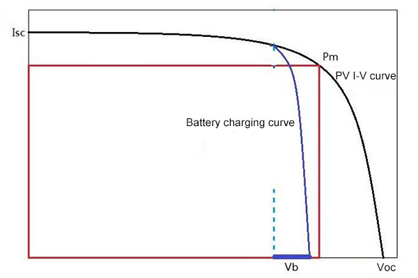 Figure 2: Switch type controller I-V curve
The multi-stage switching controller has a better charging effect than the single-stage controller. Figure 3 shows a typical four-stage controller that divides the PV modules into several groups. It adopts multiple controllers to charge the battery. Each controller can be set with different disconnection voltages so that the purpose of step current charging can be realized. The charging effect of such a controller is significantly higher than that of the single-stage controller. Such a control scheme is usually used in small and medium-sized power plants below 10 kW.
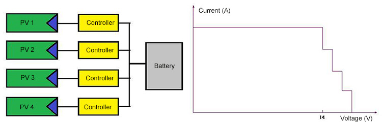 Figure 3: 4 - stage controller and charging current diagram
Pulse width modulation (PMW) charge controller
The pulse width modulation type (PMW) control means is a charging and discharging controller that automatically controls the output voltage and current according to the charging status of the battery, and adopts the pulse width duty ratio. It can fully utilize the photovoltaic power generation to efficiently charge the battery, and guarantee almost no wasted energy. If the maximum power point tracking (MPPT) circuit is set at the mating end with the photovoltaic module, the controllers of this category can have a control efficiency of more than 97%. Since such a controller uses pulsating current to charge, the instantaneous voltage of the pulsating charging is high, which can effectively avoid the suspended animation and sleeping status of the battery. Moreover, it even has a repairing and activating effect on the ordinary lead-acid battery. When the battery is almost fully charged, the pulse width modulation controller can gradually reduce the duty cycle of the output pulse width and still maintain a sufficient charging voltage. However, it can reduce the charging current to the battery according to the charging status of the battery. Adopting a similar "trickle charge" can greatly improve the charging effect and improve the service life of the battery at the same time. The voltage loss of the PWM charging circuit is low, and the charging efficiency is 3%-6% higher than that of the ordinary switching type. Therefore, the technology has been widely applied, and the problem of battery dissatisfaction can be solved. The charging conversion efficiency is 75 to 80%.
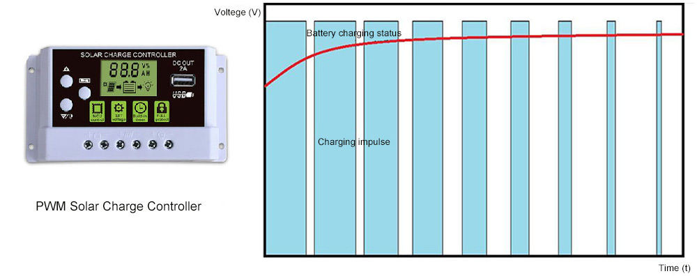
Figure 4: PWM charge controller working principle
Maximum power point tracing (MPPT) charge controller
The PMW technology solves the problem of efficient charging, but the output of the PV module is still affected by the charging state of the battery. The PV module cannot work at the maximum power point, showing that the power generation efficiency of the PV module is not really reflected. Maximum Power Point Tracking (MPPT) technology ensures that the output of the PV module is always in the best status and is not affected by the battery voltage. The MPPT solar controller can detect the solar panel voltage and current in real-time, and keep on tracking the maximum power (P=U*I) so that the system can always charge the battery with maximum power. The MPPT tracking efficiency is 99%, and the power generating efficiency of the whole system is as high as 97%. This charging process can be divided into MPPT charging, constant voltage equalizing charging and constant voltage floating charging. It adopts the MPPT charging and discharging controller, and the input voltage has a wide scope, so the voltage for the PV module is no longer the dedicated off-grid component required by the early off-grid PV power station. The PV module or component string voltages only need to reach the controller input voltage scope or MPPT voltage scope. The combination of MPPT technology and PMW technology is also a hot spot for the development of the photovoltaic controller.
Intelligent controller
With the development of electronic and computer technologies, microcomputer technology has also been widely used in the control system of the PV power generation system. The intelligent controller usually adopts the MPPT technology and PMW technology. The intelligent PV controller adopts the high-speed CPU microprocessor and high-precision A/D analog-to-digital converter and other related circuits, to charge the battery through multiple-loop solar energy battery array and carry out the intelligent automatic control to the solar energy inverter load. The data acquisition and monitoring control system of the microcomputer provides convenience for collecting and storing real-time PV off grid system data and working status. The intelligent PV controller also has a communication data transmission function, which provides the operation platform for data telemetry, centralized management, and remote control of PV stations. Through using innovative maximum power tracking technology, the PV controller can ensure maximum efficiency of solar arrays throughout the day and in any climate condition. The work efficiency of the PV module can be increased by 30% (The efficiency can be increased by 10%-25% on average).
Since the battery capacity and the charging and discharging voltage are closely related to the battery temperature, the charging and discharging controller generally has a temperature compensation function, to adapt to different environmental operating temperatures and set a more reasonable charging voltage for the battery. The temperature compensation value is generally -20~40mV/°C.
Another function of the charging and discharging controller is over-discharge control protection, ie voltage terminating protection in the over-discharge situation. Most batteries do not allow excessive discharge, which can lead to severe degradation in battery performance and service life. The over-discharge controller is usually an electronic switch. When the battery discharge voltage is lower than the set value, the load circuit is cut off and the discharge is stopped to achieve the purpose of protecting the battery. The battery discharge protection setting value is usually determined according to the type and performance of the battery. For example, the voltage of the 12V lead-acid battery over-discharge protection point is generally set to: 11.10V, the over-discharge protection point voltage of the 24V system is 22.20V, and the cut-off voltage of the single lithium battery is set to about 3.2V.