With the rapid development of renewable energy technology, solar energy, as a clean and renewable energy source, is gaining increasing popularity. In solar power generation systems, off-grid inverters serve as critical components, with their performance directly impacting the overall system's efficiency and stability. Home Power Inverter will delve into the topic of "How to test off-grid solar inverters," exploring the working principles, schematic diagrams, and testing procedures for off-grid inverters.
How does an off-grid inverter work?
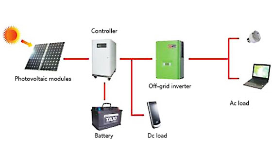
Off-grid inverters are crucial components of solar photovoltaic (PV) power generation systems. Their primary function is to convert direct current (DC) produced by solar panels into alternating current (AC) to meet the electricity needs of homes or businesses. Solar inverters in these systems convert DC to AC, providing stable power for household appliances. Solar inverters are mainly categorized into off-grid inverters and grid-tied inverters. Grid-tied inverters need to be connected to the grid to function, while off-grid inverters can generate power independently at any time, without requiring a grid connection. The working principle of off-grid inverters is based on power electronics and control theory, and can be divided into the following components:
- Input Circuit: The input circuit is the starting part of the off-grid inverter, primarily responsible for connecting the DC generated by solar panels to the inverter. The input circuit typically includes a blocking diode and a DC switch to prevent reverse current flow and protect the inverter.
- DC Voltage Boost Circuit: Since the DC voltage generated by solar panels is relatively low and insufficient for the inverter's requirements, a DC voltage boost circuit is needed to increase the voltage. This circuit usually employs a Boost converter, which adjusts the output voltage by controlling the on-off time of the switching transistor.
- Inverter Circuit: The inverter circuit is the core part of the off-grid inverter, converting DC into AC. This circuit usually adopts a full-bridge inverter design, consisting of four switching transistors and an output capacitor. By controlling the switching transistors to turn on and off in a specific sequence, AC voltage and current are generated across the output capacitor.
- Output Filter Circuit: The output filter circuit processes the AC output from the inverter to reduce harmonic distortion and noise. This circuit typically uses an LC filter, comprising an inductor and a capacitor. By adjusting the values of the inductor and capacitor, the harmonic distortion and noise in the output voltage and current can be minimized.
- Control Circuit: The control circuit is a critical part of the off-grid inverter. It automatically adjusts the on-off times of the switching transistors based on variations in parameters such as input voltage, output voltage, and current to maintain stable output voltage and current. The control circuit typically employs a PID (Proportional-Integral-Derivative) control algorithm, which adjusts the switching times by comparing the actual values with the set values and compensating for any deviations.
Working principle diagram of off-grid inverter:
How to test off-grid solar inverters?
Testing off-grid solar inverters involves several key aspects to ensure they function properly and reliably. Here are the main areas to focus on:
- Input Voltage Test: First, we need to test whether the inverter's input voltage is within the normal range. Use a multimeter or a voltmeter to measure the DC voltage output from the solar panels, ensuring it falls within the inverter's input voltage range.
- Output Voltage and Current Test: Next, we need to test whether the inverter's output voltage and current meet the required specifications. Use an AC voltmeter and ammeter to measure the inverter's AC output voltage and current, ensuring they comply with design specifications and usage requirements.
- Efficiency and Power Test: Efficiency is a crucial performance indicator of an inverter, reflecting its ability to convert DC to AC. Use instruments such as a power meter to measure the inverter's input and output power, thereby calculating its efficiency. Additionally, test the inverter's power output under different load conditions to ensure it meets various usage needs.
- Waveform Quality Test: Waveform quality is an important parameter of the solar inverter's AC output, reflecting the stability and purity of the output current. Use an oscilloscope to observe the inverter's AC output waveform, ensuring it approximates a sine wave with low harmonic distortion.
- Protection Function Test: Finally, we need to test whether the inverter's protection functions are working correctly. Simulate abnormal conditions such as overvoltage, undervoltage, overcurrent, and overtemperature to observe whether the inverter can promptly cut off output and protect itself safely.
By following these testing steps, we can comprehensively understand the performance of the off-grid solar inverter, ensuring it works stably and reliably in practical use.
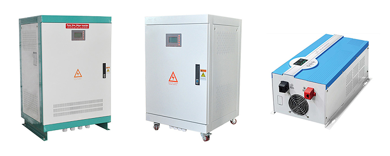
Pure sine wave off-grid solar inverter test
- Preparation
1. Shutdown of Inverter: Prior to conducting tests, ensure to shut down the inverter, disconnecting it from external power sources and the solar power system to guarantee safety throughout the testing process.
2. Connection Inspection: Thoroughly inspect all connections of the inverter to ensure their firmness, particularly checking the connections of solar panels and battery packs to avoid inaccuracies in testing or equipment damage due to connection issues.
- Static Testing
1. Input Voltage Testing: Utilize a multimeter to measure the input voltage of the inverter, ensuring it complies with equipment specifications and falls within the rated range.
2. Output Voltage Testing: Switch the multimeter to AC voltage measurement mode, connect it to the AC output terminals of the inverter, and measure the output voltage. Verify whether the output aligns with expected values based on the inverter's rated power and output specifications.
- Dynamic Testing
1. Waveform Testing: Employ an oscilloscope to test the output waveform of the inverter. In normal circumstances, the output waveform of a pure sine wave inverter should be a pure sine wave. Irregular waveforms, significant fluctuations, obvious flat tops, or sharp edges indicate potential issues with the inverter.
2. Load Capacity Testing: Connect the inverter to load devices (such as resistive loads or actual usage loads) and inspect the output stability and load adaptation capabilities of the inverter under various load conditions. Gradually increase the load and observe whether the inverter's output remains stable and if it can function normally with underrated loads.
- Performance Testing
Practical Application Testing: Connect the inverter to appliances such as household electrical appliances via loads and examine whether the output exhibits noise, maintains stable brightness, or encounters interference. If the appliances operate smoothly, it indicates good performance and stability of the inverter.
Inverter.com has two kinds of solar off-grid inverters, one is a multifunctional inverter/charger, from 700W to 6000W, DC12V/24V/48V input, 120V/220V/230V AC output, combined with inverter and battery charger function. Another version is a 3-phase with power from 8kW to 200kW.
Off-grid solar inverters are one of the key components in solar photovoltaic power generation systems, with their performance directly affecting the overall efficiency and stability of the system. By gaining an in-depth understanding of the working principles and schematic diagrams of off-grid inverters, as well as mastering the correct testing methods, we can ensure that they perform optimally in practical use, thereby contributing to the development of renewable energy.