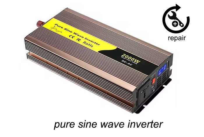
Pure sine wave inverter applications in the long term, it is inevitable due to the combined effect of a number of internal and external factors and the emergence of certain failure, thus affecting the normal use of the device. Then, we need to find specialized service personnel to repair the fault detection. This article will introduce the pure sine wave inverter during repair.

Step 1: Diagnosis and Identification of the Problem
Before attempting any repair, it's crucial to accurately diagnose the problem. This step involves a systematic approach to identify the fault in the pure sine inverter.
a. Visual Inspection
Start with a thorough visual inspection of the pure sine wave inverter. Look for any obvious signs of damage, such as burnt components, loose connections, or damaged wiring. Check for any physical signs of wear and tear that might indicate where the problem lies.
b. Testing with Multimeter
Using a multimeter, measure the voltage at various points in the circuit to pinpoint where the issue might be. Check the input voltage from the battery and the output voltage of the inverter. Ensure the pure sine wave power inverter is receiving the correct input voltage and that the output is within the expected range.
Input Voltage Check: Ensure the battery voltage is correct and that connections are secure.
Output Voltage Check: Measure the output voltage to confirm it matches the specifications of the inverter.
c. Component Testing
Identify and test individual components such as transistors, capacitors, and diodes. These components often fail due to overheating or electrical surges. Use the multimeter to check for continuity and proper functionality.
- Transistors: Check for any signs of damage or overheating.
- Capacitors: Test for capacitance and any potential leaks.
- Diodes: Ensure they are conducting correctly and not damaged.
By systematically diagnosing the problem, you can avoid unnecessary repairs and focus on the exact issue affecting the sine wave inverter.
Step 2: Replacing Faulty Components
Once the problem has been identified, the next step is to replace the faulty components. This requires precision and care to ensure the new components are installed correctly and the pure sine inverter functions as intended.
a. Sourcing Replacement Parts
Obtain high-quality replacement parts that match the specifications of the original components. Using substandard parts can lead to further issues and reduce the lifespan of the inverter. It's advisable to source parts from reputable suppliers to ensure reliability.
b. Desoldering and Removing Faulty Components
Using a soldering iron and desoldering pump or braid, carefully remove the faulty components from the circuit board. Take care not to damage the circuit board or other nearby components.
- Soldering Iron: Heat the solder joints and use the desoldering pump to remove the molten solder.
- Desoldering Braid: Place the braid on the solder joint and heat it with the soldering iron to absorb the solder.
c. Installing New Components
Place the new components in the correct positions on the circuit board and solder them in place. Ensure that the solder joints are clean and secure, providing a solid electrical connection.
- Component Placement: Insert the new components, ensuring correct orientation.
- Soldering: Apply solder to the joints, ensuring a good connection without creating bridges between adjacent pads.
After replacing the faulty components, visually inspect the circuit board to ensure everything is properly installed and there are no stray solder blobs or loose connections.
Step 3: Testing and Calibration
The final step in repairing a pure sine wave inverter is testing and calibration. This ensures the inverter is functioning correctly and providing the necessary output.
a. Initial Power-Up
After replacing the faulty components, power up the pure sine wave inverter and observe its operation. Check for any abnormal behavior, such as excessive heat, noise, or incorrect output voltage.
b. Functional Testing
Connect the sine wave inverter to a test load and measure the output voltage and waveform. Use an oscilloscope to verify the output is a pure sine wave and within the specified voltage range.
- Oscilloscope: Verify the output waveform is a pure sine wave.
- Voltage Measurement: Ensure the output voltage is within the specified range.
c. Calibration
If necessary, calibrate the pure sine wave power inverter to ensure it meets the manufacturer's specifications. This might involve adjusting potentiometers or other calibration points within the inverter.
- Adjustments: Fine-tune the inverter to match the desired output characteristics.
- Verification: Confirm the output matches the specifications after calibration.
d. Final Checks
Perform a final visual inspection and functional test to ensure the inverter is operating correctly. Check for any remaining issues and address them as needed.
- Visual Inspection: Ensure all components are secure and correctly installed.
- Functional Test: Verify the inverter's performance under different loads.
Repairing a pure sine wave inverter involves a systematic approach to diagnosing, replacing faulty components, and testing the device to ensure it operates correctly. By following these three essential steps, you can effectively repair your inverter and restore it to optimal functionality. Regular maintenance and timely repairs can significantly extend the life of your inverter, providing reliable power for your sensitive electronic equipment. If you have any question, Inverter Shop will do our best to help you solve.
