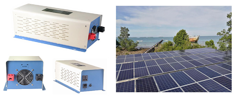
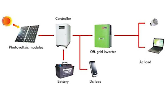
The photovoltaic off-grid power generation system is mainly used to solve the basic electricity consumption problem for residents in areas without electricity or insufficient electricity. The photovoltaic off-grid power generation system is mainly constituted of the photovoltaic component, bracket, controller, power inverter, storage battery, and power distribution system. Compared with the photovoltaic grid-connected system, the off-grid system has an additional controller and storage battery. In addition, the inverter directly drives the load, so the electrical system is more complicated. Since the off-grid system may be the only power source of the user and the user relies more on the system, the off-grid solar system design and operation must be more reliable.
Common design problems of the off-grid solar system
The photovoltaic off-grid system has no uniform specification and it must be designed according to the user demand. The model selection and calculation of components, solar inverters, controllers, batteries, cables, switches, and other equipment are mainly considered. Before the design, in order to do a good job in the preliminary work, it is required to understand the user's load type and power, the climatic condition of the installation site, and the electricity consumption of the user. After making clear the demand, the scheme can be well compiled.
1. The voltage of the component and the voltage of the battery should be matched. The PWM controller solar module and the storage battery are connected by an electronic switch, without an inductance equipment in the middle. The voltage of the component is between 1.2 and 2.0 times the voltage of the battery. If the battery has a voltage of 24V, the input voltage of the component is within 30-50V. The MPPT controller has a power switch tube and an inductor circuit in the middle. The voltage of the component is about 1.2-3.5 times the voltage of the battery. If the battery has a voltage of 24V, the component input voltage is within 30-90V.
2. The output power of the component must approach that of the controller. For example, in the case of a 48V 30A charge controller with an output power of 1440VA, the power of the component should be around 1500W. In selecting the controller, please first check the voltage of the battery, and then divide the component power by the voltage of the battery, which is exactly the output current of the controller.
3. If the power of one inverter is insufficient, multiple inverters must be connected in parallel. The output of the photovoltaic off-grid system is connected to the load. The voltage, current phase, and amplitude of each inverter output terminal are different. If the solar inverter is connected in parallel with the output terminal, it is required to add an inverter with the parallel operation function.
Common problems occurred in off-grid solar system debugging
1. The inverter LCD has no display
Fault analysis: There is no battery current input. The power inverter LCD power source is supplied by the battery.
Possible reason:
- The battery voltage is not enough. When the battery is just delivered out of the factory, it is usually fully charged. However, if the battery is not used for a long time, it will be slowly discharged (self-discharge). The off-grid system has voltage of 12V, 24V, 48V, 96V, and so on. Some applications require multiple batteries in series to meet the system voltage. If the cable is not well connected, the battery voltage will be insufficient.
- The battery terminal is reversely connected. The battery terminal has positive and negative poles. Generally, the red is connected with the positive pole and the black is connected with the negative pole.
- The DC switch is not connected or the switch has a fault.
Solution:
- If the battery voltage is not enough, the system can't work and the solar energy can't charge the battery. Then, it is required to go to another place to charge the battery to over 30%.
- If there is a problem with the circuit, please measure the voltage of each battery with a multimeter voltage gear. When the voltage is normal, the total voltage is the sum of various battery voltages. If there is no voltage, check whether the DC switch, terminal block, cable connector, and so on are normal one by one.
- If the battery voltage is normal, the wiring is normal and the switch is also turned on, but the power inverter still has no display, it may be the problem of the inverter. Then, it is required to notify the manufacturer for maintenance.
2. The battery is unable to be charged
Fault analysis: The battery is charged through the photovoltaic module and controller, or through the mains supply and controller.
Possible reason:
- Component reason: The component voltage is not sufficient, the sunshine is low, and the component and DC cable are not well wired.
- The battery circuit is not well wired.
- The battery has been fully charged and reached the highest voltage.
Solution:
- Check whether the DC switch, terminal block, cable connector, component, battery, and off-grid inverter are normal. If there are multiple components, they must be tested separately.
- When the battery reaches full charge, it can't be recharged. However, the voltage is different when different batteries are fully charged. For example, for the battery with a rated voltage of 12V, the voltage is between 12.8 and 13.5V when it is fully charged, which is related to the electrolyte proportion when the battery is fully charged. The maximum pressure limit should be adjusted according to the battery model.
- Input overcurrent: The charging current of the battery is generally 0.1C-0.2C, and the maximum does not exceed 0.3C. For example, as to a lead-acid battery 12V200AH, the charging current is generally between 20A and 40A, and can not exceed 60A to the maximum. The component power must be matched to the controller power.
- Input overvoltage: If the component input voltage is too high, the voltage of the solar panel needs to be checked. If it is really high, the possible cause is that the number of strings in the panel is too large, and the number of strings must be reduced.
3. Inverter display overload or unable to be started
Fault analysis: The load power is greater than the inverter or battery power.
Possible reason:
- Inverter overload: If the power inverter overload exceeds the time scope, the load power exceeds the maximum value, please adjust the load.
- Battery overload: The discharge current is generally 0.2C-0.3C, and the maximum value does not exceed 0.5C. As to one 12V200AH lead-acid battery, the output maximum power does not exceed 2400W. As to the batteries of different manufacturers and different models, the specific values are also different.
- The load is a load such as an elevator that cannot be directly connected to the output terminal of the inverter. When the elevator is descending, the motor reverses, and a back electromotive force is generated in entering the inverter, the inverter is damaged. If an off-grid system must be used, it is recommended to add a frequency converter between the power inverter and the elevator motor.
- The inductive load start-up power is too high.
Solution: The rated power of the load must be lower than the power of the inverter power, and the peak power of the load cannot be greater than 1.5 times the rated power of the inverter.