A centrifugal pump is one of the most widely used types of pumps in various industries, from water treatment and wastewater management to food processing and oil extraction. Its design, operational efficiency, and reliability make it an indispensable tool in modern engineering and fluid handling applications. In this article, we'll take a detailed look at the working principle of a centrifugal pump, its main components, the fluid dynamics behind its operation, and its applications across different fields.
How does a centrifugal pump work?
Centrifugal pump is a pumping machine that uses the centrifugal movement of water to work. Its basic components are a high-speed rotating impeller and a fixed snail-shaped pump casing. Generally, centrifugal pumps have several (usually 4-12) impellers with backward curved blades fastened to the pump shaft, and the impeller is driven by the motor to rotate at a high speed along with the pump shaft.
The impeller is the energy supply device of the centrifugal pump and is a component that directly performs work on the liquid in the pump. The suction port in the center of the pump casing is connected with the suction pipe, and the bottom of the suction pipe is equipped with a one-way bottom valve. The discharge port on the side of the pump casing is connected with the discharge pipe equipped with a regulating valve.
Centrifugal pumps work by using the centrifugal force generated by the rotation of the impeller. Before starting the centrifugal pump, the pump casing and suction pipe must be filled with water, and then the motor is started, so that the pump shaft drives the impeller and water to make high-speed rotation. Under the action of centrifugal force, the water is thrown to the outer edge of the impeller, and flows into the pressurized water pipeline of the water pump through the flow passage of the volute pump casing. At the center of the pump impeller, because the water is thrown out under the action of centrifugal force to form a vacuum, the water in the suction pool is pressed into the pump casing under the action of atmospheric pressure. The impeller rotates continuously, so that the water flows in and out continuously under the action of the impeller, and finally achieves the purpose of transporting water.
When water is thrown from the center of the impeller to the outer periphery, a low pressure area will be formed in the center of the impeller. Under the action of the total potential energy difference between the liquid level of the storage tank and the center of the impeller, water is sucked into the center of the impeller. Relying on the continuous operation of the impeller, water is continuously sucked and discharged. The mechanical energy obtained by the liquid in the centrifugal pump is ultimately manifested as an increase in static pressure energy.
Main components of the centrifugal pump
Impeller
The impeller is the core component of the pump, which allows the water to obtain kinetic energy to produce flow. The impeller consists of blades, cover plates and hubs. When choosing the impeller material, in addition to considering the mechanical strength under centrifugal force, the wear and corrosion resistance of the material should also be considered. At present, most impellers are made of cast iron, cast steel and bronze. Impellers can generally be divided into single-suction impellers and double-suction impellers. The single-suction impeller absorbs water on one side, and the front cover and the rear cover of the impeller are asymmetrical. The double-suction impeller absorbs water on both sides, and the impeller cover is symmetrical. Generally, large flow centrifugal pumps mostly use double-suction impellers.
Pump shaft
The pump shaft is used to rotate the pump impeller. The commonly used materials are carbon steel and stainless steel. The pump shaft should have sufficient torsion strength and sufficient rigidity, and its deflection should not exceed the allowable value. The impeller and shaft are connected by keys. The key is the connecting piece between the rotating body. Generally, flat keys are used in centrifugal pumps, which can only transmit torque and cannot fix the axial position of the impeller. In large and medium-sized water pumps, the axial position of the impeller is usually located by a shaft sleeve and a nut that tightens the shaft sleeve.
Pump casing
The water passing part requires good hydraulic conditions. When the water pump and pumping station are designed and calculated, and the impeller is working, the flow rate gradually increases along the gradually expanding section of the volute. In order to reduce the hydraulic loss, in the design of the centrifugal pump, the speed of the water flowing along the gradually expanded section of the volute should be constant. After the water is discharged from the volute, it flows into the pressurized water pipe through the tapered diffuser. The role of the tapered diffuser on the volute is to reduce the speed of the water flow, so that a part of the flow head is converted into a pressure head. As for the material selection of the pump casing, in addition to considering the corrosion and wear of the medium to the overflow part, the casing should also have sufficient mechanical strength as a pressure vessel.
Fluid dynamics in a centrifugal pump
The fluid dynamics of a centrifugal pump can be explained by the Bernoulli and Euler equations, which describe how energy is transferred from the impeller to the fluid. Here's a brief explanation of these dynamics:
- Centrifugal Force. When the impeller spins, it creates a centrifugal force that pushes the fluid radially outward. This force propels the fluid from the center of the impeller towards the edges.
- Velocity Increase. As fluid moves towards the outer edge of the impeller, its velocity increases due to the impeller's rotational speed.
- Pressure Conversion. The increase in kinetic energy (velocity) as fluid moves outward is transformed into pressure energy as the fluid flows through the pump's casing. This conversion follows the Bernoulli principle, where an increase in fluid speed results in a corresponding increase in pressure.
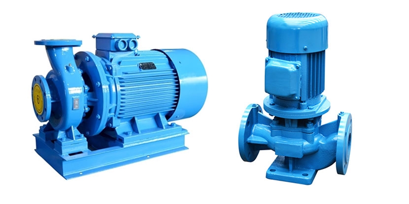
Centrifugal pumps are fundamental components in the movement and distribution of fluids across numerous industries. Their ability to efficiently convert rotational kinetic energy into pressure energy through the principle of centrifugal force makes them suitable for diverse applications. Inverter.com provides different type of centrifugal pump, such as horizontal centrifugal pump and vertical centrifugal pump. With a solid understanding of their working principles, engineers and technicians can make informed decisions when selecting and operating centrifugal pumps for optimal performance.