As to the photovoltaic grid-tie inverter, the input end is connected to the photovoltaic component and the output end is connected to the power grid. The component has only positive and negative poles, and it is not easy to wire incorrectly. Since the component is a certain distance away from the inverter, it is required to add an extension cable. The correct connection method is that the photovoltaic connector has a female connector on one side and a male connector on the other side, so that the positive and negative directions will not change. However, some green hands will also make the two connectors of the extension cable the same. If the power inverter is connected, the positive and negative poles will be reversed. The inverter AC output line and single-phase inverter have three lines: One phase line, one zero line and one ground line. The three-phase inverter usually has five lines: Three phase lines, one zero line and one ground wire. A small part of the medium voltage grid tie power inverters have four lines: Three phase lines and one ground line. The experienced installation master will not take the wrong, but the green hands sometimes make mistakes.
Influence of wrongly connecting the components
1. The on grid inverter only has one string
The on grid inverter is powered by the component. If there is only one string, the positive and negative poles are reversed, the inverter cannot be started, and the indicator light and screen of the inverter can not be turned on. However, the grid tie solar inverter will not be damaged. If it is changed and then connected, the inverter will work normally.
2. The on grid inverter has one MPPT and two strings
If both strings are reversed, as in the above case, the on grid inverter cannot be started, and the indicator light and screen of the inverter can not be turned on. If there are two strings, but one string is correctly connected but the other string is reversed, the two strings are equivalent to internal short circuit. If the component short-circuit current is amplified by 15%, the fuse will not blow. This MPPT voltage is very low and cannot generate electricity. The grid on inverter will not be damaged, but the component will burn out slowly, which may cause fire.
3. The on grid inverter has one MPPT and several strings
If the strings are reversed, as in the above case, the inverter cannot be started, and the indicator light and screen of the power inverter can not be turned on. If one string is connected accurately, and the other strings are reversed, or one string is reversedm and the other strings are connected accurately, the strings will have short-circuit inside. The current will multiply by over 2 times. If the power inverter has a fuse protector, the fuse protector will fuse and the circuit disconnects, but it will not cause fire. After the fuse is blown, the voltage on the two ends of the fuse doubles, causing overvoltage damage to the solar on grid inverter.
If the components are reversed, the consequences are more serious. In not serious conditions, the grid tie power inverter will be damaged. In serious conditions, the component may cause fire. Therefore, it should be paid with great attention. If the green hand is not very skilled, it is suggested to use a multimeter to measure the voltage in the first. Be sure to use the DC voltage file. If the directions of the measured voltage and inverter are correct, it can be connected to the power inverter.

Influence of wrong wired AC output terminal
If the AC line is connected incorrectly, the power inverter will probably be unable to be started, some protection functions will miss, but the inverter will not be damaged. The following paragraph is a brief analysis of the wrong wired situation.
1. The sequence of three phase lines (A, B, C lines). There is no problem of wrong connection, because the grid-tie inverter has the function of automatically adjusting the phase sequence. Before the grid-tie power generation, please firstly take electricity from the grid, detect the voltage, frequency, phase sequence and other parameters of the power grid, and then adjust the parameters of the power generation. After synchronizing with the electrical parameters of the power grid, grid-connected power generation will be realized.
2. The phase line and the neutral line are connected incorrectly. At this time, the on grid inverter will report the grid voltage fault. The inverter A phase will display the line voltage of 380V. B and C will display the phase voltage of 220V. The grid connected inverter is unable to be started because of the too low voltage.
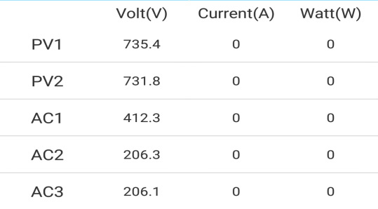
The above figure is the voltage of each phase of the grid seen from the APP monitoring when the power inverter reports the grid voltage over-range warning. The AC1 is normal, the AC2 and AC3 voltages are low. After on-site detection, it can be found that the phase line L1 and the zero line N are reversed.
3. The ground line and the zero line are reversed. The ground line and zero line will be connected together when they reach the transformer end. As to the three-phase converter current, the zero line and the ground line basically have no current. However, when the inverter terminal is wired, they can not be connected together because they play different roles. The main role of the ground line is lightning protection safety, inverter reference potential, anti-electromagnetic interference shielding grounding, anti-component PID and so on. The role of the zero line is to constitute one loop with the phase line. The single-phase zero line has current, and if the three-phase system is unbalanced, the zero line will also have current as well. If the zero line and the ground line are reversed, these functions of the ground line are gone, and there may be failures such as lightning damage, inaccurate AC voltage measurement, and vulnerability of the power inverter. The ground line of the single-phase inverter may be charged, and the inverter casing may be charged. There may be an electric shock accident, and the leakage protector might trip because of an error.
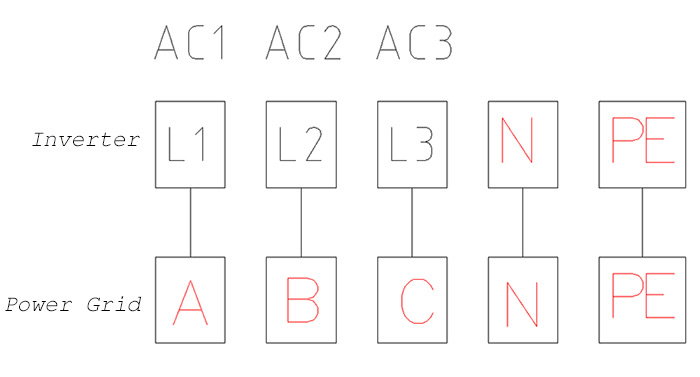
The three phase low voltage grid on inverter generally adopts the three-phase five-wire system, including three phase lines of three-phase power (A, B, C lines), a neutral line (N line), and a ground line (PE line). The ground line is connected to the neutral line on the power supply transformer side, but cannot be used as a neutral line after entering the user side. The voltage between the phase lines of the power supply line (ie, the line voltage) is 380V, and the voltage between the phase line and the ground or neutral line (ie, the phase voltage) is 220V. The entry line generally adopts the single-phase three-wire system, that is, one of the three phase lines, neutral line (zero line) and ground line. National standard, the three-phase five-wire standard wire has the color as follows: A line yellow, B line green, C line red, N line blue, PE line yellow and green. The AC output lines of the grid tie inverters are generally arranged in the order of A, B, C, N, and PE. Therefore, you will certainly make no mistakes if you wire according to the colors stipulated by the national standard.