Full name of the micro inverter is micro solar on grid inverter. It generally refers to inverters with power below 1500W and module-level MPPT. It is mostly used in photovoltaic power generation systems. Micro is relatively small compared to traditional centralized inverters. The micro inverter inverts each component. Its advantage is that each component can be independently controlled by MPPT, which can greatly improve the overall efficiency. At the same time, micro inverter can also avoid the DC high voltage, poor light effect, and wooden barrel effect of the centralized inverter.
Basic Concept of Power Conversion:
At its core, power conversion involves changing electrical energy from one form to another. Solar panels produce DC electricity when exposed to sunlight, but most electrical appliances and the grid operate on AC. Therefore, an inverter is needed to convert the DC output from solar panels into usable AC. Micro grid inverters perform this function at the individual panel level, as opposed to string inverters which handle the conversion for a series of panels collectively.
Conversion Process:
- Step 1: DC to DC Conversion. The process begins with the DC-DC converter. The voltage output from a solar panel can vary widely depending on the amount of sunlight and the load connected to the panel. The DC-DC converter stabilizes this voltage to a level suitable for the inverter circuit. This stabilization is achieved through techniques such as buck (step-down) or boost (step-up) conversion. The goal is to ensure that the inverter receives a consistent input voltage, which is crucial for efficient operation.
- Step 2: DC to AC Inversion. Once the DC voltage is stabilized, the inverter circuit converts it to AC. This conversion is typically performed using a full-bridge or half-bridge inverter topology, where semiconductor switches are rapidly turned on and off to create an AC waveform. The switching frequency is often several kilohertz, and the resultant waveform is a series of pulses that approximate a sine wave.
- Step 3: Filtering. The raw AC output from the inverter circuit is not suitable for direct use because it contains high-frequency components due to the switching process. A filter composed of inductors and capacitors smooths out these components, resulting in a clean sine wave that can be used by AC appliances or fed into the grid.
- Step 4: Synchronization and Control. The final step involves synchronization and control. The inverter must synchronize its output with the frequency and phase of the grid to ensure seamless integration. The controller manages this process, adjusting the phase and frequency of the inverter's output as necessary. Additionally, the controller implements MPPT algorithms to maximize the power harvested from each solar panel, adapting to changing environmental conditions to optimize performance.
Solar cell micro inverters manage the collection of solar energy at the level of a single panel to improve the efficiency of the solar equipment, rather than working in the entire system like a central inverter. In the past, in order to ensure maximum power output during solar energy harvesting, the complex control mechanisms used increased costs and restricted the acceptance of micro-inverters. Complex and cost-effective IC and processor-based solutions can handle the logic control of pv micro inverter designs. Various voltage controllers and regulators also provide complementary solutions for solar panel DC output power generation.
In terms of function, the micro inverter is a DC/AC power source driven by the output of a solar panel. It relies on the familiar voltage converter topology to maximize power conversion efficiency. For the design of micro inverters, forward and flyback converters are still the most commonly used DC/DC conversion topologies. Silicon controlled rectifiers (SCR) or MOSFET full bridges are used to generate AC waveforms at the required grid frequency (shown as the following figure).
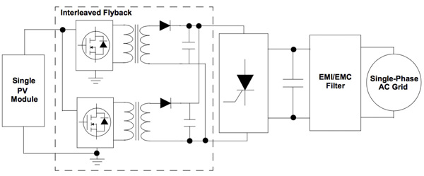
In a simple micro inverter design, the interleaved active clamp flyback inverter can increase the low-voltage DC voltage of the solar panel and the high-voltage AC waveform required by the power grid.
Just as the power supply design, photovoltaic micro inverter design requires various techniques to improve efficiency and reliability. It uses an interleaved flyback topology to help reduce the RMS ripple current through them to extend the life of the electrolytic capacitors in these designs. In addition, the application of active clamping technology can achieve a higher maximum duty cycle, allowing the use of higher turns ratios. This can significantly reduce the current stress on the primary side and the voltage stress on the secondary side.
In order to ensure the maximum energy output, the converter must be able to respond to the control logic of the micro inverter. The logic is designed to maintain the converter voltage and current as much as possible to keep it consistent with the ideal characteristics produced by the MPPT algorithm. More importantly, a micro grid inverter connected to the grid needs to be able to disconnect itself from the grid during a power failure. In turn, these fault protection functions require the power converter to have at least overvoltage and undervoltage detection functions.
The design of grid tie micro inverters brings requirements for control, power conversion, and efficiency, limiting their widespread acceptance in the past. However, as the availability of integrated solutions increases, designers can use a variety of suitable equipment. Although a dedicated processor can provide the advanced control functions and MPPT functions required by the microinverter, the design of the power conversion stage requires that the device can safely and efficiently provide the performance and functions required by the grid. Through a wide selection of available integrated switch controllers and PMICs, engineers can create efficient and economical power conversion stages in micro inverter designs.
Technological Innovations:
Recent advancements have further enhanced the capabilities and efficiency of micro inverters:
- Advanced MPPT Algorithms. Modern micro inverters employ sophisticated MPPT algorithms that can rapidly and accurately track the optimal operating point of each panel, even under rapidly changing environmental conditions.
- Integration with Smart Grids. Micro inverters are increasingly being designed to integrate with smart grid technologies. This integration allows for more efficient energy distribution and better grid stability.
- Wireless Communication. Advances in wireless communication technologies have enhanced the ability of smart micro inverters to transmit data, enabling more efficient monitoring and control of solar power systems.
Micro inverters represent a pivotal innovation in solar power technology, offering numerous benefits in terms of efficiency, safety, scalability, and reliability. In inverter shop, different wattage smart micro inverter are available. Their working principle, centered on converting DC from solar panels to AC for grid or household use, involves sophisticated processes and advanced components. As technology continues to evolve, solar grid tie micro inverters are likely to play an even more critical role in the adoption and optimization of solar energy systems, contributing significantly to the global shift towards renewable energy sources.