The grid tie inverter is a crucial component in the realm of renewable energy, particularly in the integration of solar power systems with the existing electrical grid. It serves as the bridge between the photovoltaic (PV) panels and the utility grid, ensuring that the electricity generated by the solar panels is efficiently and safely fed into the grid. Understanding the working principle of a solar grid-tie inverter is essential for comprehending how solar energy can be seamlessly integrated into the existing power infrastructure.
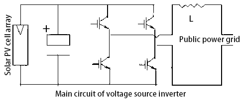
In addition to the DC-AC conversion function, the on grid tie inverter shall also own the solar cell array MPPT function and various protection function. The solar cell array delivers power energy to the power grid through sine wave PWM inverter. The power sent from the grid connected inverter to power grid is determined by the solar cell array power and local sunshine conditions of the specific time. Now, solar inverter technology becomes very mature, and the main circuit of the power inverter is shown in following figure.
The operation circuit of the grid tie solar PV system is shown in figure 2. Vp means the output voltage of the grid tie solar inverter. Vu means the grid voltage. R means the wire resistance and L means the series reactor. Iz means the current that is sent back to the grid. To ensure the feedback current power factor is always 1, the phase of the feedback current and the grid voltage shall be consistent. By referring to the grid voltage of Vu, then the phase of the Iz and Vu shall be consistent. VR, the voltage at two terminals of the internal resistance R, shall be consistent with the power grid voltage. In addition, the phase of VL, the voltage at two terminals of the reactor, is lower than that of the voltage VR. The phase and amplitude of VP can be calculated by the formula:
Vp=Iz x (R + ωL) +Vu
In the formula: ω refers to the angular frequency of the utility grid.
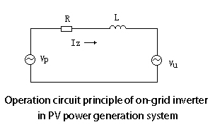
In the actual circuit of solar grid tie inverter, the phase, period and amplitude of Vu are detected by the voltage sensor. As it is difficult to get R value in actual system, the phase of feedback current Iz shall be obtained by the negative current feedback. The phase angle of the feedback current Iz is worked out by referring to the utility grid phase. The Iz shall be detected by the current transformer from time to time to ensure that Iz is consistent with the grid voltage. In thus way, the feedback power generation with the power factor of 1 can be realized.
The microprocessor is mainly used to test the real-time voltage phase, feedback and control the current phase, track the maximum power of solar cell array and track the real-time sine wave PWM signal. Its work process is as following: Though hall voltage sensor, the voltage and phase of the utility grid is sent to the A/D converter of the microprocessor. Then, the microprocessor will compare the feedback current phase and the utility grid voltage phase. The error signal will be adjusted by PID and then be sent to the pulse width modulator (PWM). In this way, the feedback process of the power with power factor of 1 is completed. Another main function of the microprocessor is to realize the maximum power output of the solar cell array. The output power of the solar cell array can be worked out by detecting the output voltage and current of the solar cell array separately by the voltage and current sensor, and then multiplying these two detected value. Then, the PWM output duty cycle shall be calculated. This is actually to adjust the feedback voltage so as to obtain the optimized maximum power.
Based on figure 2, it can be discovered that when Vp amplitude changes, the phase angle φ between the feedback current of the solar grid tie inverter and grid voltage will also change. Since the feedback control of the current phase is realized, the decoupling control of the phase and amplitude will be realized, which will make the process work of the microprocessor simpler. In addition, the work status of the grid tie solar PV system under the power-off condition shall also be considered. In the common grid tie solar PV system, when the power supply of the utility grid is stopped, the solar grid tie inverter will stop working.
The work principle: When the power supply of the utility grid is stopped, the grid side will stay in short-circuit status. At this time, the grid tie solar inverter will start self-production function because of the overload problem. When the overload situation is detected by the microprocessor, it will block the SPWM signal and will trigger the circuit breaker connected with the power grid. If the solar cell array can output energy, grid tie power inverter will operate separately, which can be controlled easily. It only needs to know the negative feedback status of the AC voltage. The microprocessor will detect the output voltage of solar grid connected inverter and compare it with the reference voltage (normally is 220V). Then, it will control the PWM output duty cycle to realize inverting and stable-voltage operation.
The precondition to ensure stable-voltage operation is that the solar cell array can provide enough power at that time. If the load is too high or the sunlight condition is poor, on grid power inverter can not output enough power and then the terminal voltage of the solar cell array will be decreased. Then, the output AC voltage will be decreased, which will cause low-voltage protection status. When the power supply of the grid is back to normal, it will switch to the feedback status automatically.
Protection Mechanisms:
Grid tie inverters are equipped with several protection mechanisms to ensure safe and reliable operation:
- Anti-Islanding Protection: Prevents the inverter from supplying power to the grid during a blackout, protecting utility workers who may be repairing the lines.
- Over-Voltage and Over-Current Protection: Safeguards the inverter and connected devices from damage due to voltage or current surges.
- Ground Fault Protection: Detects and mitigates ground faults, which could pose a risk of electric shock or fire.
Grid on inverters play a vital role in the integration of solar power systems with the electrical grid. By converting DC to AC, and ensuring safe and efficient grid synchronization, these inverters enable the seamless use of solar energy in homes and businesses. While there are challenges and considerations to account for, the benefits of using grid tie pv inverters, including high efficiency, economic savings, scalability, and environmental impact, make them a key component in the transition to renewable energy sources. As technology continues to advance, solar grid connected inverters will likely become even more efficient and accessible, further driving the adoption of solar energy worldwide.