The basic principle of a solar water pump system is to use semiconductor solar cells to convert solar energy directly into electricity, and then use various motors to drive water pumps for water lifting from deep wells, rivers, lakes, and other water sources. In some small and medium-power solar pump systems, a brushless DC motor is often used as the driving motor, but in some larger-power solar pump systems, an asynchronous AC motor is also used as the driving motor. In the case of an AC asynchronous motor as a driving motor, a solar pump inverter(solar variable frequency drive) is usually used to control.
Composition of the system
A solar pumping system is usually composed of a solar photovoltaic array, solar pump inverter, and pump. Its structure diagram is shown in Figure 1.
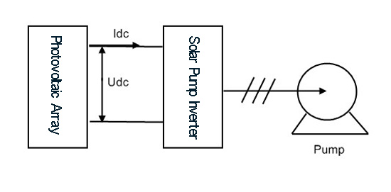
Fig. 1 Photovoltaic water pump system composition
Unlike our common water pump system which uses AC as a power supply, the solar water pump system uses DC power output from solar panels as a power supply. The output of the solar photovoltaic array is a strong non-linear DC power supply, which is greatly affected by sunshine, ambient temperature, and other meteorological factors. In order to realize the maximum output power potential of a PV array under any sunshine, ambient temperature, and other conditions, a controller that can make the power supply and load work harmoniously, efficiently, and stably is needed. The solar pump inverter in Figure 1 is to achieve this function, mainly to achieve MPPT (maximum power point tracking), inverters, and some protection functions. The pump is the executive mechanism of the system. The solar pump inverter drives the motor and water pump. The load system can be adjusted by adjusting the speed of the pump.
Working principle
The solar array is a kind of non-linear DC power supply. It is neither a constant current source nor a constant voltage source, nor can it provide any large power for the load. But under the condition of certain sunshine, the photovoltaic array has a maximum output power point. If the output power of the photovoltaic array is the corresponding power value of that point, the system works in the optimal state at this time. Fig. 2 shows the I-V curves of solar PV arrays under different sunshine intensities
Figure 2: S is sunshine intensity in W/m2. A, B, C, D, and E are the maximum output power points of photovoltaic arrays under the corresponding sunshine intensity.
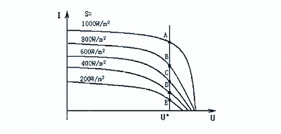
Fig. 2 Schematic diagram of CVT MPPT
In CVT MPPT, the maximum output power points (A, B, C, D, E points in Figure 2) under different sunshine intensities can be approximated as a straight line U = U* = const in engineering. That is to say, as long as the photovoltaic array keeps its output voltage at U*=const during the operation of the solar water pump system, it can ensure that the photovoltaic array has the maximum power output under the current sunshine.
Using solar variable frequency drive to drive solar water pump to realize CVT MPPT control is based on the feedback control principle. Under different sunshine intensities, the speed of the motor pump (i.e. load size) is adjusted by changing the output frequency of the solar pump inverter, to stabilize the output voltage of the photovoltaic array. The control principle is shown in Figure 3.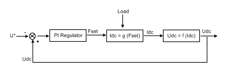
Fig. 3 System control schematic diagram
Fig. 3: U* is the given value of the PI regulator and also the given instruction voltage of CVT. Udc is the actual output voltage of the photovoltaic array and also the DC side voltage of the solar pump inverter. Fset is the given value of the solar pump inverter. Idc is the output current of the photovoltaic array and also the DC side current of the solar pump inverter.
In Figure 3, the PI regulator outputs the frequency signal of the solar pump inverter according to the given error, thus changing the speed of the motor, that is, changing the load size of the system. The larger the Fset, the higher the motor speed and the larger the system load. Conversely, the smaller the Fset, the lower the motor speed and the smaller the system load. The system load directly affects the DC side current of the solar pump inverter, that is, the size of Idc. The larger the load, the larger the Idc, the smaller the load, the smaller the Idc. This constitutes the system regulation process described below:
When the output voltage Udc of the photovoltaic array is greater than the instruction voltage U*, the frequency of the solar pump inverter increases with the given Fset, the speed N of the pump increases, the load increases, the output current Idc of the photovoltaic array increases, and the output voltage Udc of photovoltaic array decreases until it stabilizes at the working point U*. When the output voltage Udc of the photovoltaic array is less than the instruction U*, the frequency of the converter given Fset decreases, the speed N of the pump decreases, the load decreases, the output current Idc of photovoltaic array decreases, and the output voltage Udc of photovoltaic array increases until it stabilizes at the working point U*.
Solar pump system is one of the most characteristic application fields in solar PV applications. Inverter.com sells DC/AC single-phase solar pump inverters and three phase solar pump inverters with favorable prices, power capacity from 1/2hp 0.4kw, 1hp 0.75kw, 2hp 1.5kw to 50hp 37kw, widely used in solar water pump systems. The system is simple in composition and easy to debug, and requires no special sampling unit and protection unit (They are all realized by the internal functions of the solar pump inverter), can realize full-automatic control, is suitable for use in some remote and dry areas.