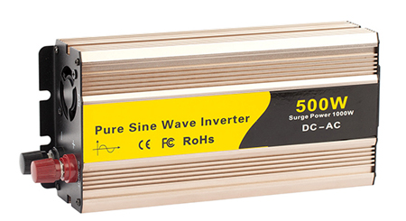
When you want to use a pure sine wave inverter to power electronic equipment in your home, you must understand how the equipment works. Inverters are not only used during power outages and power outages but can also be used outdoors. The inverter has power sockets through which you can connect electrical appliances.
How does a pure sine wave inverter work?
- DC input: The pure sine inverter receives DC power from a power source such as a battery or solar panel. This input power is typically at a lower voltage, such as 12V, 24V, or 48V.
- Oscillator circuit: The oscillator circuit generates a high-frequency AC signal. This signal serves as a reference for creating a pure sine wave. Precision in the oscillator circuit is essential to minimize harmonic distortion and ensure a consistent, high-quality AC output, suitable for sensitive electronics. Advanced designs may incorporate feedback mechanisms to adjust the waveform in real-time, ensuring stability and accuracy under varying load conditions.
- Pulse width modulation (PWM): The high-frequency AC signal from the oscillator is fed into a PWM controller. The PWM controller adjusts the width of the pulses to accurately represent a sine wave. By varying the width of these pulses, the controller creates a series of pulses that approximate the desired sine wave shape.
- H-bridge inverter: The modulated pulses are fed into an H-bridge inverter circuit consisting of four switching transistors or MOSFETs.The H-bridge configuration allows the DC input to be converted to an AC output. The switches in the H-bridge are controlled in such a way that the output alternates between positive and negative voltages, creating a rough AC waveform.
- Filtering: The rough AC waveform produced by the H-bridge inverter passes through a low-pass filter, usually consisting of an inductor and capacitor. This filter smoothes the high-frequency pulses and shapes them into a clean sine wave.
- Feedback and control: The feedback control system constantly monitors the output waveform and makes adjustments to the PWM signal to ensure that the output remains a pure sine wave. This involves comparing the output to a reference sine wave and correcting any deviations.
- AC output: The filtered and controlled AC output is now a pure sine wave suitable for powering sensitive electronic equipment and appliances. The output voltage and frequency are typically regulated to match the local utility standards.
Three different phases of the pure sine wave inverter operation
- Oscillation phase: The pure sine wave power inverter generates pulses as it passes through the IC circuit. The resulting voltage will have a specific frequency. Both negative and positive voltages will oscillate at a specific frequency. These weak signals make it difficult to power high-current output transformers. You can increase the strength of weak signals by setting up an amplifier. It improves the signal and allows the inverter to perform its tasks.
- Booster or amplifier stage: The voltage produced by the oscillator will be amplified using an amplifier and bring the low current level to the operating level. The amplified power will be in AC form. However, the voltage is provided by the battery, which is too low for the appliance to operate. You can increase the voltage level to allow the device to function optimally by amplifying the voltage level. This increased voltage is passed to the secondary winding of the output transformer.
- Output transformer stage: The transformer will lower the AC level with the help of magnetic induction. Transformers act as power inverters, but not vice versa. The lower AC power in the amplifier stage is passed to the secondary winding of the transformer in the output stage. The voltage rises, which the pure sine wave solar power inverter uses to power the AC equipment connected to it.
Key Components
- Oscillator: An oscillator in a pure sine wave inverter generates a stable, continuous sine wave signal that determines the inverter's output frequency. It uses components like quartz crystals to maintain precise frequency, ensuring efficient and consistent conversion of DC to a pure AC sine wave.
- PWM controller: The PWM controller uses the high-frequency signal from the oscillator to create a series of high-frequency pulses that simulate a sine wave.
- H-bridge: The H-bridge inverter switches the DC voltage at high frequency, creating a high-frequency AC signal.
- Low-pass filter: Smooths the rough AC into a pure sine wave.
- Feedback system: Ensures the output remains a clean sine wave.
Pure sine wave inverters play a crucial role in modern power conversion applications, providing clean, stable, and high-quality AC power from DC sources. Their ability to mimic the utility-supplied electricity makes them indispensable for sensitive electronic devices and critical applications. By understanding the components and operational principles of pure sine wave inverters, we can appreciate their advantages and the wide range of applications they support. As technology continues to advance, the efficiency and capabilities of pure sine wave inverters are likely to improve, further enhancing their role in our increasingly electrified world. If you have any question, Inverter.com will do our best to help you.